学校代码:10246 学号: 062052038 復旦大¥ 硕士学位论文 射频接收机中模拟信道滤波器设计 院 系: 微电子学系 专 业: 微电子学与固体电子学 姓 名: 邹亮 指导教师: 唐长文副教授 完成日期: 2009年5月22日
学校代码: 10246 学 号: 062052038 硕 士 学 位 论 文 射频接收机中模拟信道滤波器设计 院 系: 微电子学系 专 业: 微电子学与固体电子学 姓 名: 邹亮 指 导 教 师: 唐长文 副教授 完 成 日 期: 2009 年 5 月 22 日

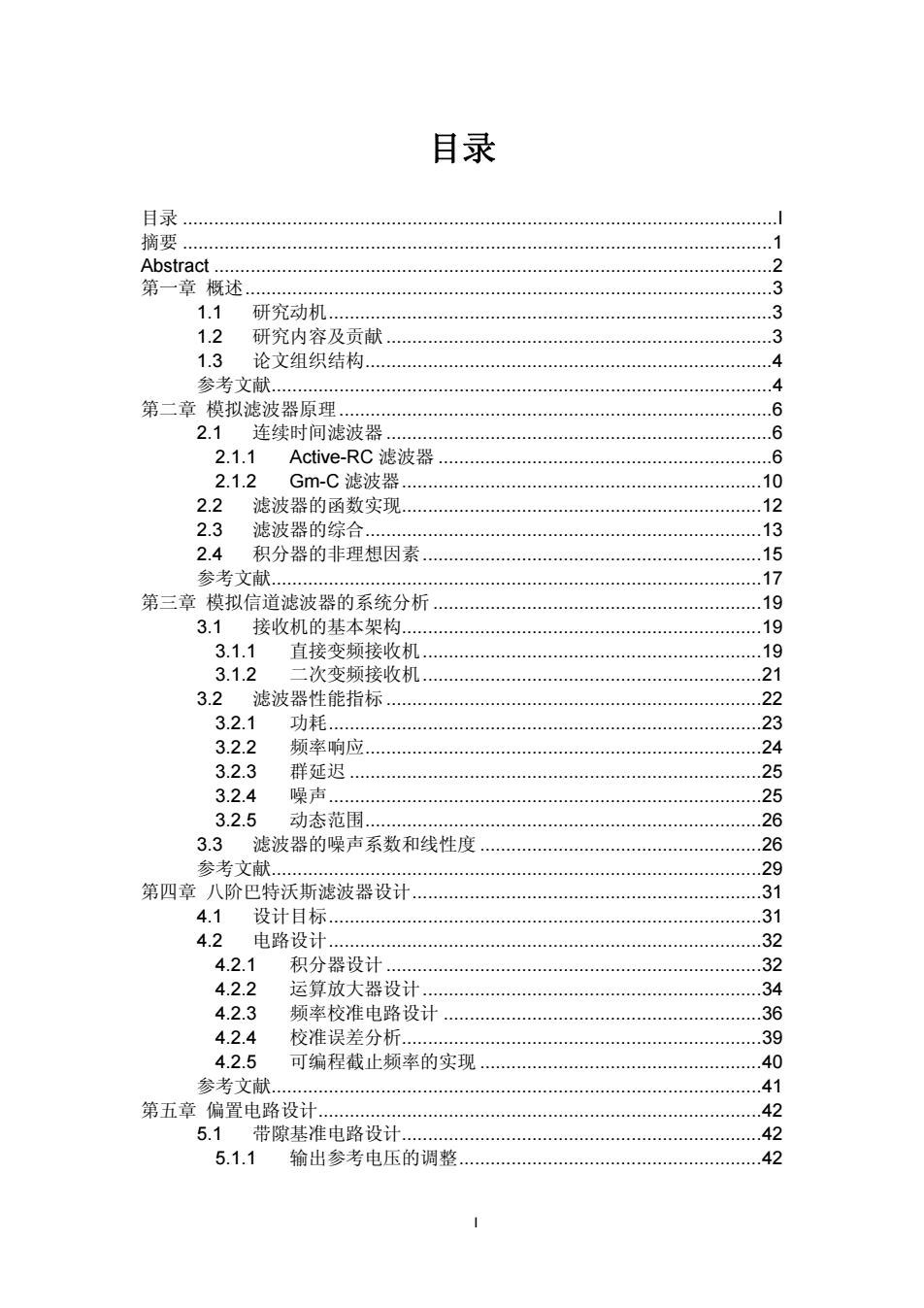
目录 目录 摘要 Abstract .2 第一章概述 3 1.1 研究动机.… .3 1.2 研究内容及贡献 .3 1.3 论文组织结构… 又 参考文献, 4 第二章模拟滤波器原理 2.1连续时间滤波器... ⑥ 2.1.1 Active-RC滤波器 6 2.1.2 Gm-C滤波器.. .10 2.2滤波器的函数实现. .12 2.3 滤波器的综合. ..13 2.4 积分器的非理想因素 .15 17 参若义.… 第三章模拟信道滤波器的系统分析. .19 3.1接收机的基本架构.… 19 3.1.1 直接变频接收机 .19 3.1.2 二次变频接收机 .21 3.2滤波器性能指标 .22 3.2.1 功耗 23 3.2.2 频率响应 .24 3.2.3 群延迟 .25 3.2.4 噪声 .25 3.2.5 动态范围. .26 3.3滤波器的噪声系数和线性度 .26 参考文献, .29 第四章八阶巴特沃斯滤波器设计 .31 4.1设计目标 31 4.2 电路设计 .32 4.2.1 积分器设计 .32 4.2.2 运算放大器设计.. .34 4.2.3 频率校准电路设计 .36 4.2.4 校准误差分析... .39 4.2.5 可编程截止频率的实现 .40 参考文献 .41 第五章偏置电路设计 .42 5.1带隙基准电路设计 .42 5.1.1 输出参考电压的调整...… .42
I 目录 目录 ..................................................................................................................I 摘要 .................................................................................................................1 Abstract ...........................................................................................................2 第一章 概述.....................................................................................................3 1.1 研究动机.....................................................................................3 1.2 研究内容及贡献..........................................................................3 1.3 论文组织结构..............................................................................4 参考文献................................................................................................4 第二章 模拟滤波器原理...................................................................................6 2.1 连续时间滤波器..........................................................................6 2.1.1 Active-RC 滤波器 ................................................................6 2.1.2 Gm-C 滤波器.....................................................................10 2.2 滤波器的函数实现.....................................................................12 2.3 滤波器的综合............................................................................13 2.4 积分器的非理想因素.................................................................15 参考文献..............................................................................................17 第三章 模拟信道滤波器的系统分析 ...............................................................19 3.1 接收机的基本架构.....................................................................19 3.1.1 直接变频接收机.................................................................19 3.1.2 二次变频接收机.................................................................21 3.2 滤波器性能指标........................................................................22 3.2.1 功耗...................................................................................23 3.2.2 频率响应............................................................................24 3.2.3 群延迟 ...............................................................................25 3.2.4 噪声...................................................................................25 3.2.5 动态范围............................................................................26 3.3 滤波器的噪声系数和线性度 ......................................................26 参考文献..............................................................................................29 第四章 八阶巴特沃斯滤波器设计...................................................................31 4.1 设计目标...................................................................................31 4.2 电路设计...................................................................................32 4.2.1 积分器设计........................................................................32 4.2.2 运算放大器设计.................................................................34 4.2.3 频率校准电路设计 .............................................................36 4.2.4 校准误差分析.....................................................................39 4.2.5 可编程截止频率的实现 ......................................................40 参考文献..............................................................................................41 第五章 偏置电路设计.....................................................................................42 5.1 带隙基准电路设计.....................................................................42 5.1.1 输出参考电压的调整..........................................................42

5.1.2 温度系数分析. .44 5.1.3 电路设计… 45 5.1.4 噪声分析 45 5.1.5 仿真结果 .47 5.1.6 偏置电流… .48 5.2低压差线性稳压器设计 ...49 5.2.1 电源抑制比分析 .49 5.2.2 噪声分析… .50 5.2.3 电路实现 52 5.2.4 仿真结果 54 参考文献 55 第六章芯片实现及测试 .57 6.1芯片实现.. .57 6.2 测试PCB设计… .58 6.3 芯片测试结果 .59 6.3.1 偏置电路测试结果 .59 6.3.2 滤波器测试结果 .60 6.4测试分析与改进 64 参考文献 67 第七章总结与展望 68 7.1总结 68 7.2 未来展望 .68 参考文献 .68 致谢 .69
II 5.1.2 温度系数分析.....................................................................44 5.1.3 电路设计............................................................................45 5.1.4 噪声分析............................................................................45 5.1.5 仿真结果............................................................................47 5.1.6 偏置电流............................................................................48 5.2 低压差线性稳压器设计 .............................................................49 5.2.1 电源抑制比分析.................................................................49 5.2.2 噪声分析............................................................................50 5.2.3 电路实现............................................................................52 5.2.4 仿真结果............................................................................54 参考文献..............................................................................................55 第六章 芯片实现及测试.................................................................................57 6.1 芯片实现...................................................................................57 6.2 测试 PCB 设计..........................................................................58 6.3 芯片测试结果............................................................................59 6.3.1 偏置电路测试结果 .............................................................59 6.3.2 滤波器测试结果.................................................................60 6.4 测试分析与改进........................................................................64 参考文献..............................................................................................67 第七章 总结与展望 ........................................................................................68 7.1 总结..........................................................................................68 7.2 未来展望...................................................................................68 参考文献..............................................................................................68 致谢 ...............................................................................................................69

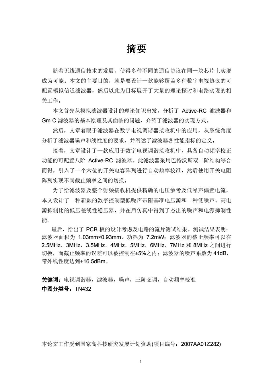
摘要 随着无线通信技术的发展,使得多种不同的通信协议在同一块芯片上实现 成为可能。本文的主要目的,就是要设计一款能够覆盖多种数字电视协议的可 配置模拟信道滤波器,然后以此为目标展开了大量的理论探讨和电路实现的相 关工作。 本文首先从模拟滤波器设计的理论知识出发,分析了Active-RC滤波器和 G-C滤波器的基本原理及其面临的问题,介绍了滤波器的实现方式。 然后,文章着眼于滤波器在数字电视调谐器接收机中的应用,从系统角度 分析了滤波器噪声和线性度的要求,并阐述了滤波器各性能指标的定义。 接着,文章设计了一款应用于数字电视调谐接收机中,具备自动频率校正 功能的可配置八阶Active-RC滤波器。此滤波器采用巴特沃斯双二阶结构综合 而得,引入了一个六位的开关电容阵列进行自动频率校准,然后使用开关电阻 阵列实现不同截止频率之间的切换。 为了给滤波器及整个射频接收机提供精确的电压参考及低噪声偏置电流, 本文设计了一种新颖的数字控制型低噪声带隙基准电压源和一种低噪声、高电 源抑制比的低压差线性稳压器,并在后仿真中得到了杰出的噪声和电源抑制性 能。 最后,给出了PCB板的设计考虑及电路的流片测试结果。测试结果表明: 滤波器面积为1.03mm×0.93mm,功耗为7.2mW:滤波器的截止频率可以在 2.5MHz,3MHz,3.5MHz,4MHz,5MHz,6MHz,7MHz和8MHz之间进行 切换,而截止频率的误差可以被控制在±5%之内:滤波器的噪声系数为41dB, 带外线性度达到+16.5dBm。 关键词:电视调谐器,滤波器,噪声,三阶交调,自动频率校准 中图分类号:TN432 本论文工作受到国家高科技研究发展计划资助(项目编号:2007AA01Z282)
1 摘要 随着无线通信技术的发展,使得多种不同的通信协议在同一块芯片上实现 成为可能。本文的主要目的,就是要设计一款能够覆盖多种数字电视协议的可 配置模拟信道滤波器,然后以此为目标展开了大量的理论探讨和电路实现的相 关工作。 本文首先从模拟滤波器设计的理论知识出发,分析了 Active-RC 滤波器和 Gm-C 滤波器的基本原理及其面临的问题,介绍了滤波器的实现方式。 然后,文章着眼于滤波器在数字电视调谐器接收机中的应用,从系统角度 分析了滤波器噪声和线性度的要求,并阐述了滤波器各性能指标的定义。 接着,文章设计了一款应用于数字电视调谐接收机中,具备自动频率校正 功能的可配置八阶 Active-RC 滤波器。此滤波器采用巴特沃斯双二阶结构综合 而得,引入了一个六位的开关电容阵列进行自动频率校准,然后使用开关电阻 阵列实现不同截止频率之间的切换。 为了给滤波器及整个射频接收机提供精确的电压参考及低噪声偏置电流, 本文设计了一种新颖的数字控制型低噪声带隙基准电压源和一种低噪声、高电 源抑制比的低压差线性稳压器,并在后仿真中得到了杰出的噪声和电源抑制性 能。 最后,给出了 PCB 板的设计考虑及电路的流片测试结果。测试结果表明: 滤波器面积为 1.03mm×0.93mm,功耗为 7.2mW;滤波器的截止频率可以在 2.5MHz,3MHz,3.5MHz,4MHz,5MHz,6MHz,7MHz 和 8MHz 之间进行 切换,而截止频率的误差可以被控制在±5%之内;滤波器的噪声系数为 41dB, 带外线性度达到+16.5dBm。 关键词:电视调谐器,滤波器,噪声,三阶交调,自动频率校准 中图分类号:TN432 本论文工作受到国家高科技研究发展计划资助(项目编号:2007AA01Z282)

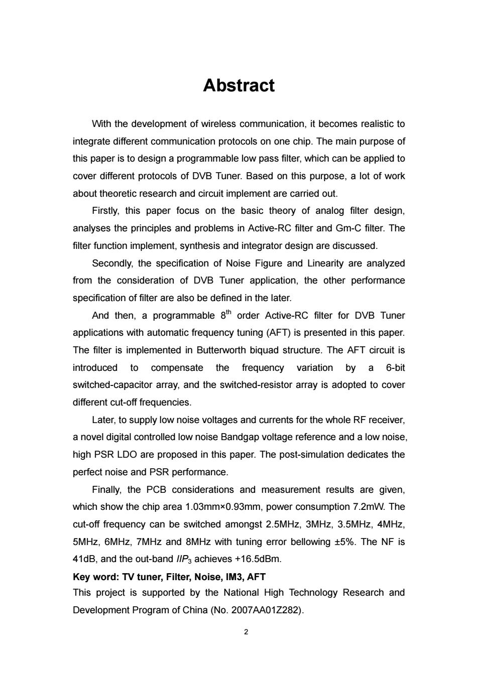
Abstract With the development of wireless communication,it becomes realistic to integrate different communication protocols on one chip.The main purpose of this paper is to design a programmable low pass filter,which can be applied to cover different protocols of DVB Tuner.Based on this purpose,a lot of work about theoretic research and circuit implement are carried out. Firstly,this paper focus on the basic theory of analog filter design, analyses the principles and problems in Active-RC filter and Gm-C filter.The filter function implement,synthesis and integrator design are discussed. Secondly,the specification of Noise Figure and Linearity are analyzed from the consideration of DVB Tuner application,the other performance specification of filter are also be defined in the later. And then,a programmable 8th order Active-RC filter for DVB Tuner applications with automatic frequency tuning(AFT)is presented in this paper. The filter is implemented in Butterworth biquad structure.The AFT circuit is introduced to compensate the frequency variation by a 6-bit switched-capacitor array,and the switched-resistor array is adopted to cover different cut-off frequencies. Later,to supply low noise voltages and currents for the whole RF receiver, a novel digital controlled low noise Bandgap voltage reference and a low noise, high PSR LDO are proposed in this paper.The post-simulation dedicates the perfect noise and PSR performance. Finally,the PCB considerations and measurement results are given, which show the chip area 1.03mmx0.93mm,power consumption 7.2mW.The cut-off frequency can be switched amongst 2.5MHz,3MHz,3.5MHz,4MHz, 5MHz,6MHz,7MHz and 8MHz with tuning error bellowing t5%.The NF is 41dB,and the out-band //P3 achieves +16.5dBm. Key word:TV tuner,Filter,Noise,IM3,AFT This project is supported by the National High Technology Research and Development Program of China(No.2007AA01Z282) 2
2 Abstract With the development of wireless communication, it becomes realistic to integrate different communication protocols on one chip. The main purpose of this paper is to design a programmable low pass filter, which can be applied to cover different protocols of DVB Tuner. Based on this purpose, a lot of work about theoretic research and circuit implement are carried out. Firstly, this paper focus on the basic theory of analog filter design, analyses the principles and problems in Active-RC filter and Gm-C filter. The filter function implement, synthesis and integrator design are discussed. Secondly, the specification of Noise Figure and Linearity are analyzed from the consideration of DVB Tuner application, the other performance specification of filter are also be defined in the later. And then, a programmable 8th order Active-RC filter for DVB Tuner applications with automatic frequency tuning (AFT) is presented in this paper. The filter is implemented in Butterworth biquad structure. The AFT circuit is introduced to compensate the frequency variation by a 6-bit switched-capacitor array, and the switched-resistor array is adopted to cover different cut-off frequencies. Later, to supply low noise voltages and currents for the whole RF receiver, a novel digital controlled low noise Bandgap voltage reference and a low noise, high PSR LDO are proposed in this paper. The post-simulation dedicates the perfect noise and PSR performance. Finally, the PCB considerations and measurement results are given, which show the chip area 1.03mm×0.93mm, power consumption 7.2mW. The cut-off frequency can be switched amongst 2.5MHz, 3MHz, 3.5MHz, 4MHz, 5MHz, 6MHz, 7MHz and 8MHz with tuning error bellowing ±5%. The NF is 41dB, and the out-band IIP3 achieves +16.5dBm. Key word: TV tuner, Filter, Noise, IM3, AFT This project is supported by the National High Technology Research and Development Program of China (No. 2007AA01Z282)