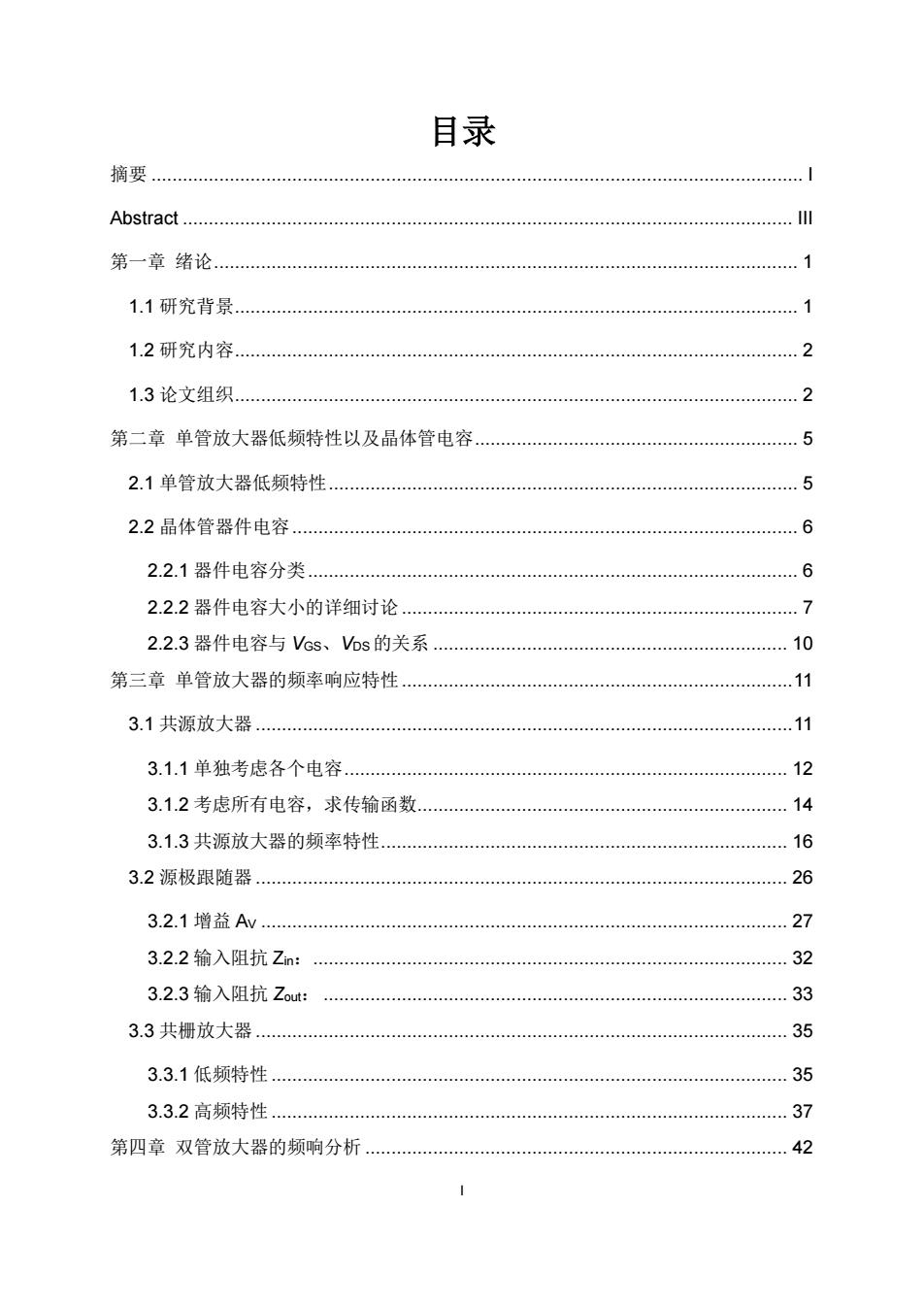
目录 摘要 Abstract. 第一章绪论. 1 1.1研究背景.… 7 1.2研究内容..… 。。 2 1.3论文组织 。。 2 第二章单管放大器低频特性以及晶体管电容 5 2.1单管放大器低频特性 5 2.2晶体管器件电容 6 2.2.1器件电容分类 6 2.2.2器件电容大小的详细讨论 2.2.3器件电容与Vcs、VDs的关系. 10 第三章单管放大器的频率响应特性 .11 3.1共源放大器 .11 3.1.1单独考虑各个电容.… 12 3.1.2考虑所有电容,求传输函数 14 3.1.3共源放大器的频率特性 16 3.2源极跟随器. 26 3.2.1增益Av. 27 3.2.2输入阻抗Zin: 32 3.2.3输入阻抗Zout: 33 3.3共栅放大器 35 3.3.1低频特性 35 3.3.2高频特性 37 第四章双管放大器的频响分析.… 42
I 目录 摘要 ............................................................................................................................. I Abstract ..................................................................................................................... III 第一章 绪论................................................................................................................ 1 1.1 研究背景............................................................................................................ 1 1.2 研究内容............................................................................................................ 2 1.3 论文组织............................................................................................................ 2 第二章 单管放大器低频特性以及晶体管电容.............................................................. 5 2.1 单管放大器低频特性.......................................................................................... 5 2.2 晶体管器件电容................................................................................................. 6 2.2.1 器件电容分类.............................................................................................. 6 2.2.2 器件电容大小的详细讨论 ............................................................................ 7 2.2.3 器件电容与 VGS、VDS 的关系 .................................................................... 10 第三章 单管放大器的频率响应特性...........................................................................11 3.1 共源放大器 .......................................................................................................11 3.1.1 单独考虑各个电容..................................................................................... 12 3.1.2 考虑所有电容,求传输函数....................................................................... 14 3.1.3 共源放大器的频率特性.............................................................................. 16 3.2 源极跟随器 ...................................................................................................... 26 3.2.1 增益 AV ..................................................................................................... 27 3.2.2 输入阻抗 Zin:........................................................................................... 32 3.2.3 输入阻抗 Zout: ......................................................................................... 33 3.3 共栅放大器 ...................................................................................................... 35 3.3.1 低频特性................................................................................................... 35 3.3.2 高频特性................................................................................................... 37 第四章 双管放大器的频响分析 ................................................................................. 42

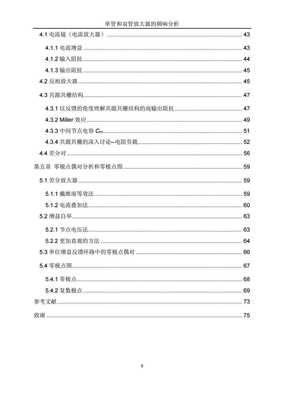
单管和双管放大器的频响分析 4.1电流镜(电流放大器) 43 4.1.1电流增益 43 4.1.2输入阻抗 44 4.1.3输出阻抗 45 4.2反相放大器 45 4.3共源共栅结构 47 4.3.1以反馈的角度理解共源共栅结构的高输出阻抗 47 4.3.2 Miller效应 49 4.3.3中间节点电容Cm... 51 4.3.4共源共栅的深入讨论-电阻负载. 52 4.4差分对...… 56 第五章零极点偶对分析和零极点图 59 5.1差分放大器 59 5.1.1戴维南等效法 59 5.1.2电流叠加法 60 5.2增益自举, 63 5.2.1节点电压法 63 5.2.2更加直观的方法 64 5.3单位增益反馈环路中的零极点偶对 66 5.4零极点图 67 5.4.1零极点 68 5.4.2复数极点 69 参考文献. 73 致谢 75
单管和双管放大器的频响分析 II 4.1 电流镜(电流放大器) .................................................................................... 43 4.1.1 电流增益................................................................................................... 43 4.1.2 输入阻抗................................................................................................... 44 4.1.3 输出阻抗................................................................................................... 45 4.2 反相放大器 ...................................................................................................... 45 4.3 共源共栅结构................................................................................................... 47 4.3.1 以反馈的角度理解共源共栅结构的高输出阻抗.......................................... 47 4.3.2 Miller 效应................................................................................................. 49 4.3.3 中间节点电容 Cm....................................................................................... 51 4.3.4 共源共栅的深入讨论--电阻负载................................................................. 52 4.4 差分对 ............................................................................................................. 56 第五章 零极点偶对分析和零极点图.......................................................................... 59 5.1 差分放大器 ...................................................................................................... 59 5.1.1 戴维南等效法............................................................................................ 59 5.1.2 电流叠加法................................................................................................ 60 5.2 增益自举.......................................................................................................... 63 5.2.1 节点电压法................................................................................................ 63 5.2.2 更加直观的方法 ........................................................................................ 64 5.3 单位增益反馈环路中的零极点偶对 .................................................................. 66 5.4 零极点图.......................................................................................................... 67 5.4.1 零极点....................................................................................................... 68 5.4.2 复数极点................................................................................................... 69 参考文献 ................................................................................................................... 73 致谢 .......................................................................................................................... 75

摘要 模拟集成电路设计必须在多种参数之间进行折中。大多数情况下,速度和包括增益、 功率、噪声等在内的其他参数是相互影响的。同时,由于对高速电路的强劲需求,如何 将模拟电路设计推向更高频率一直挑战着设计者。因此,理解各种电路的频率响应和速 度限制因素是十分必要的。 绝大多数模拟电路是由差分对、电流镜等基本电路单元构成的,本论文只考察这些 基本电路。他们通常包含两个节点,有时包含三个节点,因此传输函数是两阶的,有时 是三阶的。两阶系统可以代表绝大多数放大器,因此被详细讨论。在本文中,基本放大 器根据包含的晶体管数目划分为,单管放大器:共源放大器、源极跟随器(共漏放大器)、 共栅放大器:双管放大器:电流镜、反相放大器、共源共栅放大器和差分对。 本文完成工作: 在推导上述基本电路的传输函数表达式时我们使用了一定技巧:首先使用节点分析 法得到各节点方程,然后利用克莱姆法则求解矩阵方程组。利用波特图和零极点位置图 来研究高频特性。为研究电路中某个指定参数对频率特性的影响,以该参数的不同取值 重复作波特图多次。零极点位置图给出了以某个指定参数为变量的指定传输函数的零极 点变化。它为分析该参数对高频特性的影响提供了有力工具,也可以清楚地解释不稳定 区域、零极点抵消点等概念。 首先,本文回顾了单管放大器的低频特性和包含器件电容的晶体管高频小信号模型。 其次,分析了单管放大器的频率特性。虽然看起来过于简单,但是单管放大器已经包含 两个极点,可以代表所有的两阶放大器。源极跟随器可用作阻抗转换级,将仔细研究它 的从高阻抗到低阻抗缓冲能力随着频率的变化。从低阻抗到高阻抗转换可以通过共栅放 大器实现。详细讨论包括增益、输入输出阻抗在内的传输函数特性。其他重要的现象, 比如极点分离在这些简单电路结构中也会涉及。然后,双管放大器的频率响应也会被详 细讨论。电流镜在构建放大器的偏置电路和有源负载方面极其重要,它的最简单的形式 由两个晶体管构成。接着讨论的是非常著名的反相放大器、共源共栅放大器和模拟电路 中最重要的基本单元电路差分对。最后,研究电流镜对差分对频率特性的影响,以及增 益自举共源共栅放大器的频率响应特性,引入了零极点偶对的概念。还将给出关于如何 作零极点位置图的详细的例子
I 摘要 模拟集成电路设计必须在多种参数之间进行折中。大多数情况下,速度和包括增益、 功率、噪声等在内的其他参数是相互影响的。同时,由于对高速电路的强劲需求,如何 将模拟电路设计推向更高频率一直挑战着设计者。因此,理解各种电路的频率响应和速 度限制因素是十分必要的。 绝大多数模拟电路是由差分对、电流镜等基本电路单元构成的,本论文只考察这些 基本电路。他们通常包含两个节点,有时包含三个节点,因此传输函数是两阶的,有时 是三阶的。两阶系统可以代表绝大多数放大器,因此被详细讨论。在本文中,基本放大 器根据包含的晶体管数目划分为,单管放大器:共源放大器、源极跟随器(共漏放大器)、 共栅放大器;双管放大器:电流镜、反相放大器、共源共栅放大器和差分对。 本文完成工作: 在推导上述基本电路的传输函数表达式时我们使用了一定技巧:首先使用节点分析 法得到各节点方程,然后利用克莱姆法则求解矩阵方程组。利用波特图和零极点位置图 来研究高频特性。为研究电路中某个指定参数对频率特性的影响,以该参数的不同取值 重复作波特图多次。零极点位置图给出了以某个指定参数为变量的指定传输函数的零极 点变化。它为分析该参数对高频特性的影响提供了有力工具,也可以清楚地解释不稳定 区域、零极点抵消点等概念。 首先,本文回顾了单管放大器的低频特性和包含器件电容的晶体管高频小信号模型。 其次,分析了单管放大器的频率特性。虽然看起来过于简单,但是单管放大器已经包含 两个极点,可以代表所有的两阶放大器。源极跟随器可用作阻抗转换级,将仔细研究它 的从高阻抗到低阻抗缓冲能力随着频率的变化。从低阻抗到高阻抗转换可以通过共栅放 大器实现。详细讨论包括增益、输入输出阻抗在内的传输函数特性。其他重要的现象, 比如极点分离在这些简单电路结构中也会涉及。然后,双管放大器的频率响应也会被详 细讨论。电流镜在构建放大器的偏置电路和有源负载方面极其重要,它的最简单的形式 由两个晶体管构成。接着讨论的是非常著名的反相放大器、共源共栅放大器和模拟电路 中最重要的基本单元电路差分对。最后,研究电流镜对差分对频率特性的影响,以及增 益自举共源共栅放大器的频率响应特性,引入了零极点偶对的概念。还将给出关于如何 作零极点位置图的详细的例子

单管和双管放大器的频响分析 关键词: 单管放大器、共源放大器、源极跟随器、共栅放大器、双管放大器、电流镜、反相 放大器、共源共栅放大器、差分对、零极点偶对、增益自举、频率响应特性、传输函数、 零极点、零极点位置图、波特图、密勒效应、正负零点 中图分类号:TN4
单管和双管放大器的频响分析 II 关键词: 单管放大器、共源放大器、源极跟随器、共栅放大器、双管放大器、电流镜、反相 放大器、共源共栅放大器、差分对、零极点偶对、增益自举、频率响应特性、传输函数、 零极点、零极点位置图、波特图、密勒效应、正负零点 中图分类号:TN4

Abstract Many parameters should be taken into consideration because there are so many different specifications in analog circuits.Nevertheless,in most cases,the speed trades with many other parameters including gain,power dissipation,and noise. Meanwhile,due to the need for increasingly higher speed circuits,the demand to push circuits to higher frequencies has always challenged designers.It is therefore necessary to understand the frequency response and speed limitations of each circuit. Most circuits are built up using elementary building blocks such as current mirrors and differential pairs,and in this thesis,only elementary circuits are considered.They have two or sometimes three nodes,and thus their transfer characteristics are second order,or occasionally third order.Second-order systems are discussed in detail because most amplifiers can be well represented by them.In the organization of this thesis,elementary transistor stages are classified by the number of transistors used or we can classify as follows.single-transistor stages:common source amplifier,source follower(common drain amplifier)and common gate amplifier;two-transistor stages: current mirror,CMOS inverter,cascode amplifier and differential pair. Skills are developed for deriving transfer functions of these elementary stages Equations at each nodes are written using the technique of nodal analysis,and then these matrix equations are solved using Cramer's approach.In order to study their high-frequency performance,Bode diagrams and pole-zero position diagrams are used throughout.Bode diagrams are repeated for several values of one single parameter to learn how that parameter in the circuit may influence the performance.A pole-zero position diagram gives the evolution of poles and zeros of a particular transfer function with one single parameter as a variable.It provides insight into the role of that parameter with respect to the high frequency performance and illustrates the regions of instability,pole-zero cancellation points,etc. First,we review the low frequency characteristics of single-transistor amplifier, transistor's high-frequency small-signal model with device capacitances and load capacitances added. 川
III Abstract Many parameters should be taken into consideration because there are so many different specifications in analog circuits. Nevertheless, in most cases, the speed trades with many other parameters including gain, power dissipation, and noise. Meanwhile, due to the need for increasingly higher speed circuits, the demand to push circuits to higher frequencies has always challenged designers. It is therefore necessary to understand the frequency response and speed limitations of each circuit. Most circuits are built up using elementary building blocks such as current mirrors and differential pairs, and in this thesis, only elementary circuits are considered. They have two or sometimes three nodes, and thus their transfer characteristics are second order, or occasionally third order. Second-order systems are discussed in detail because most amplifiers can be well represented by them. In the organization of this thesis, elementary transistor stages are classified by the number of transistors used or we can classify as follows. single-transistor stages: common source amplifier, source follower (common drain amplifier) and common gate amplifier; two-transistor stages: current mirror, CMOS inverter, cascode amplifier and differential pair. Skills are developed for deriving transfer functions of these elementary stages. Equations at each nodes are written using the technique of nodal analysis, and then these matrix equations are solved using Cramer’s approach. In order to study their high-frequency performance, Bode diagrams and pole-zero position diagrams are used throughout. Bode diagrams are repeated for several values of one single parameter to learn how that parameter in the circuit may influence the performance. A pole-zero position diagram gives the evolution of poles and zeros of a particular transfer function with one single parameter as a variable. It provides insight into the role of that parameter with respect to the high frequency performance and illustrates the regions of instability, pole-zero cancellation points, etc. First, we review the low frequency characteristics of single-transistor amplifier, transistor’s high-frequency small-signal model with device capacitances and load capacitances added