孩旦大婴 硕士学位论文 56M~806M宽频带Double-Conversion混频器设计 院 系:信息科学与工程学院 专 业: 微电子与固体电子学 姓 名: 舒适 指导教师: 闵昊教授 完成时间: 2004.5.30
I 硕 士 学 位 论 文 56M~806M 宽频带 Double-Conversion 混频器设计 院 系 : 信息科学与工程学院 专 业 : 微电子与固体电子学 姓 名 : 舒 适 指导教师 : 闵昊 教授 完成时间 : 2004.5.30

目录 ABSTRACT....... 摘要.。 II 月言,,,,,,,,,,,,,,,,,,,,,, 1.1通信系统的概念…… …1 1.2接收端的结构.…… …3 L.2.1超外差结构的接收端(Superheterodyne Receiver).......3 1.2.2零中频结构的接收端(Homodyne Receiver)... …6 l.2.3镜像抑制接收器(Image-.Reject Receivers).. ........11 1.3设计目的…… .15 1.4论文提纲.……… 16 第二章混频器的基本概念.… 17 2.1混频器的基本原理… 17 2.2混频器的性能参数........ 18 2.2.1转换增益(Conversion Gain). ..18 2.2.2噪声系数(Noise Figure)..…· 18 2.2.3线性度(Linearity)......19 2.2.4隔离度(solation)...... ..25 2.2.5输入输出阻抗匹配(nput&Output matching).......25 第三章混频器的电路结构... 27 3.1混频器的基本工作原理和分类..... 27 3.2 Active混频器.......... ....28 3.2.1基于平方关系(square-.law)的混频器 ...28 3.2.2基于乘法器(Multiplier-.Based)的混频器 30 3.3 Passive混频器............ 。。。。。。。。。。。 32 3.3.1电压混频器(Potentiometric Mixers) 32 3.3.2 Double-balanced Mixer.............. 33 3.3.3 Subsampling Mixer........... 35 第四章Upconversion宽带混频器的设计. 37 4.1VGA电路的设计及仿真..... 38
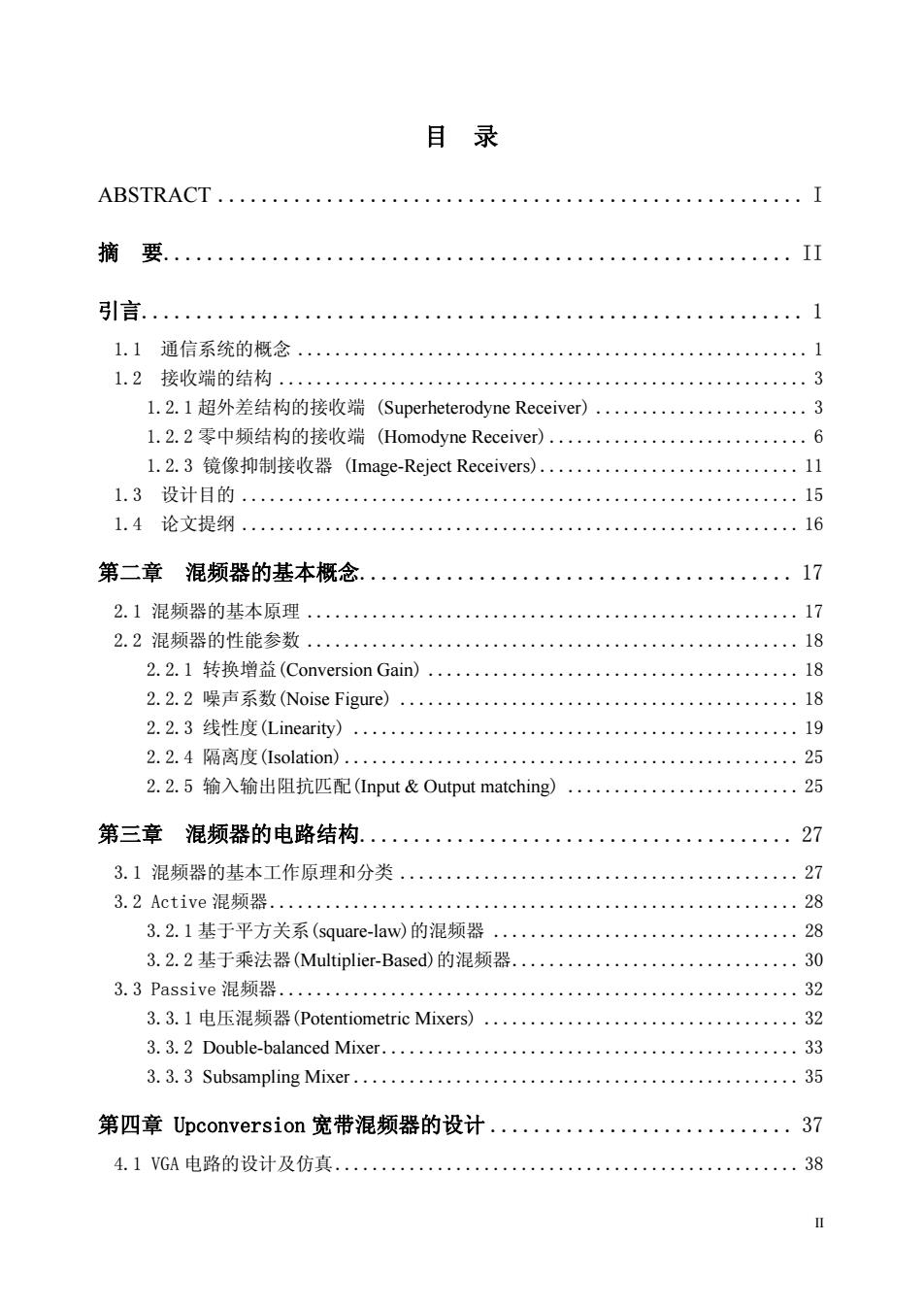
II 目 录 ABSTRACT ...................................................... I 摘 要.......................................................... II 引言............................................................. 1 1.1 通信系统的概念 ....................................................... 1 1.2 接收端的结构 ......................................................... 3 1.2.1 超外差结构的接收端 (Superheterodyne Receiver) ....................... 3 1.2.2 零中频结构的接收端 (Homodyne Receiver) ............................ 6 1.2.3 镜像抑制接收器 (Image-Reject Receivers)............................ 11 1.3 设计目的 ............................................................ 15 1.4 论文提纲 ............................................................ 16 第二章 混频器的基本概念........................................ 17 2.1 混频器的基本原理 ..................................................... 17 2.2 混频器的性能参数 ..................................................... 18 2.2.1 转换增益(Conversion Gain) ........................................ 18 2.2.2 噪声系数(Noise Figure) ........................................... 18 2.2.3 线性度(Linearity) ................................................ 19 2.2.4 隔离度(Isolation) ................................................. 25 2.2.5 输入输出阻抗匹配(Input & Output matching) ......................... 25 第三章 混频器的电路结构........................................ 27 3.1 混频器的基本工作原理和分类 ........................................... 27 3.2 Active 混频器 ......................................................... 28 3.2.1 基于平方关系(square-law)的混频器 ................................. 28 3.2.2 基于乘法器(Multiplier-Based)的混频器............................... 30 3.3 Passive 混频器 ........................................................ 32 3.3.1 电压混频器(Potentiometric Mixers) .................................. 32 3.3.2 Double-balanced Mixer............................................. 33 3.3.3 Subsampling Mixer ................................................ 35 第四章 Upconversion 宽带混频器的设计 ............................ 37 4.1 VGA 电路的设计及仿真 .................................................. 38

4.2简单Gi1bert结构混频器的设计.......................41 4.3宽带混频器线性度的提高....... 46 4.4增益,IIP3和噪声系数的简单计算 47 4.5改进的宽带上变频混频器的设计.. 48 4.6电路测试........... 51 第五章总结... 54 5.1论文总结... 54 5.2展望和建议.... 55 致谢.. 56 参考文献.. 57
III 4.2 简单 Gilbert 结构混频器的设计 .......................................... 41 4.3 宽带混频器线性度的提高 ................................................ 46 4.4 增益,IIP3 和噪声系数的简单计算 ....................................... 47 4.5 改进的宽带上变频混频器的设计 .......................................... 48 4.6 电路测试 .............................................................. 51 第五章 总结..................................................... 54 5.1 论文总结 ............................................................. 54 5.2 展望和建议 ........................................................... 55 致 谢.......................................................... 56 参考文献........................................................ 57

ABSTRACT Today,TV tuner takes a very important role in the future development of the Digital Signal Television.From cable to wireless,Digital Signal Television becomes more necessary in our life.In the TV tuner receiver system,cable signal and wireless signal can be received and decode,then transferred to digital signal and sent to backend for further signal processing. An up-conversion wide band mixer used for the TV tuner system is designed in this paper,with the frequency range from 56MHz to 806MHz and output central frequency of 1.1GHz.TV tuner adopts double conversion super-heterodyne architecture.Firstly,it converts the input wide band RF signal to a higher 1.1GHz intermediate frequency,and secondly,down-convert the 1.1GHz frequency to 44MHz intermediate frequency for DSP at backend.From the analysis and comparison of the advantage and disadvantage of the Active and Passive mixer,I decide to use Active Gilbert mixer topology,because the noise figure and conversion gain performance is better than the others,but the loss of the linearity performance must be considered.Series of linearity improvement idea are put forward and adopted in this paper to make up for the loss of the linearity performance. With the Chartered 0.35um library file and spectreRF simulation tool,my design is proved that the designed circuit can meet the system'requirement from the simulation result. The up-conversion is taped out in chartered 0.35um CMOS process.For the sake of measurement,the RF and LO bias circuit are added to the up-conversion circuit.At the end of the paper,the core measurement plan is put forward.Because the wide band match problem can not be resolved,the measurement plan is just based on the point frequency input and point frequency output,and both the input impendence and the output impendence are all 502. Keywords:up-conversion,down-conversion,Active mixer,Passive mixer,image signal
I ABSTRACT Today, TV tuner takes a very important role in the future development of the Digital Signal Television. From cable to wireless, Digital Signal Television becomes more necessary in our life. In the TV tuner receiver system, cable signal and wireless signal can be received and decode, then transferred to digital signal and sent to backend for further signal processing. An up-conversion wide band mixer used for the TV tuner system is designed in this paper, with the frequency range from 56MHz to 806MHz and output central frequency of 1.1GHz. TV tuner adopts double conversion super-heterodyne architecture. Firstly, it converts the input wide band RF signal to a higher 1.1GHz intermediate frequency, and secondly, down-convert the 1.1GHz frequency to 44MHz intermediate frequency for DSP at backend. From the analysis and comparison of the advantage and disadvantage of the Active and Passive mixer, I decide to use Active Gilbert mixer topology, because the noise figure and conversion gain performance is better than the others, but the loss of the linearity performance must be considered. Series of linearity improvement idea are put forward and adopted in this paper to make up for the loss of the linearity performance. With the Chartered 0.35um library file and spectreRF simulation tool, my design is proved that the designed circuit can meet the system’ requirement from the simulation result. The up-conversion is taped out in chartered 0.35um CMOS process. For the sake of measurement, the RF and LO bias circuit are added to the up-conversion circuit. At the end of the paper, the core measurement plan is put forward. Because the wide band match problem can not be resolved, the measurement plan is just based on the point frequency input and point frequency output, and both the input impendence and the output impendence are all 50Ω . Keywords:up-conversion, down-conversion, Active mixer, Passive mixer, image signal

摘要 TV tuner是未来数字电视发展的重要环节,从有线到无线,数字电视在我们生活中将 会越来越重要。通过TV tuner的接收系统可以将cable信号和无线信号接收并解调,转换 成数字信号,送到内部做数字信号处理。 本文主要设计了用于TV tuner系统中的上变频宽带混频器,它的工作频率为 56~806MHz,输出中频为1.1GHz。TV tuner采用两级变频的super-heterodyne结构,前 一级就是通过宽带的上变频混频器将输入的RF信号上变频到一个1.1GHz的点频附近, 然后再通过一个下变频的混频器将这个1.1GHz的点频下变频到44MHz的低频附近输出 到后面的滤波器进行进一步处理。通过对Active和Passive混频器各种电路结构优缺点的 分析和比较,最终决定混频器采用Active的Gilbert混频器结构,因为这样电路的Noise Figure和增益性能会比较好,但线性度的性能会有所损失.本文中提到并采用了一系列的 提高混频器线性度的方法,以弥补这一损失。本设计用charteredo.35um的库用spectreRF 进行仿真,仿真结果说明,这种结构完全可以满足系统的要求。 设计的上变频电路在chartered0.35 um CMOS的工艺中进行流片,为了方便测试,在 电路中加入了偏置电路为RF和LO输入端提供直流电压。在论文的最后介绍了芯片测试 的方案,由于没能解决好宽带输入阻抗匹配的问题,所以整个芯片是计划在点频输入和点 频输出的情况下进行测试,输入输出阻抗都是502。 关键字:上变频,下变频,有源混频器,无源混频器,镜像信号
II 摘 要 TV tuner 是未来数字电视发展的重要环节,从有线到无线,数字电视在我们生活中将 会越来越重要。通过 TV tuner 的接收系统可以将 cable 信号和无线信号接收并解调,转换 成数字信号,送到内部做数字信号处理。 本文主要设计了用于 TV tuner 系统中的上变频宽带混频器,它的工作频率为 56~806MHz,输出中频为 1.1GHz。TV tuner 采用两级变频的 super-heterodyne 结构,前 一级就是通过宽带的上变频混频器将输入的 RF 信号上变频到一个 1.1GHz 的点频附近, 然后再通过一个下变频的混频器将这个 1.1GHz 的点频下变频到 44MHz 的低频附近输出 到后面的滤波器进行进一步处理。通过对 Active 和 Passive 混频器各种电路结构优缺点的 分析和比较,最终决定混频器采用 Active 的 Gilbert 混频器结构,因为这样电路的 Noise Figure 和增益性能会比较好,但线性度的性能会有所损失. 本文中提到并采用了一系列的 提高混频器线性度的方法,以弥补这一损失。本设计用 chartered0.35um 的库用 spectreRF 进行仿真,仿真结果说明,这种结构完全可以满足系统的要求。 设计的上变频电路在 chartered0.35um CMOS 的工艺中进行流片,为了方便测试,在 电路中加入了偏置电路为 RF 和 LO 输入端提供直流电压。在论文的最后介绍了芯片测试 的方案,由于没能解决好宽带输入阻抗匹配的问题,所以整个芯片是计划在点频输入和点 频输出的情况下进行测试,输入输出阻抗都是 50Ω 。 关键字:上变频,下变频,有源混频器,无源混频器,镜像信号