图4-25负载电流跳变对输出电压的影响…59
V 图 4-25 负载电流跳变对输出电压的影响···················································59

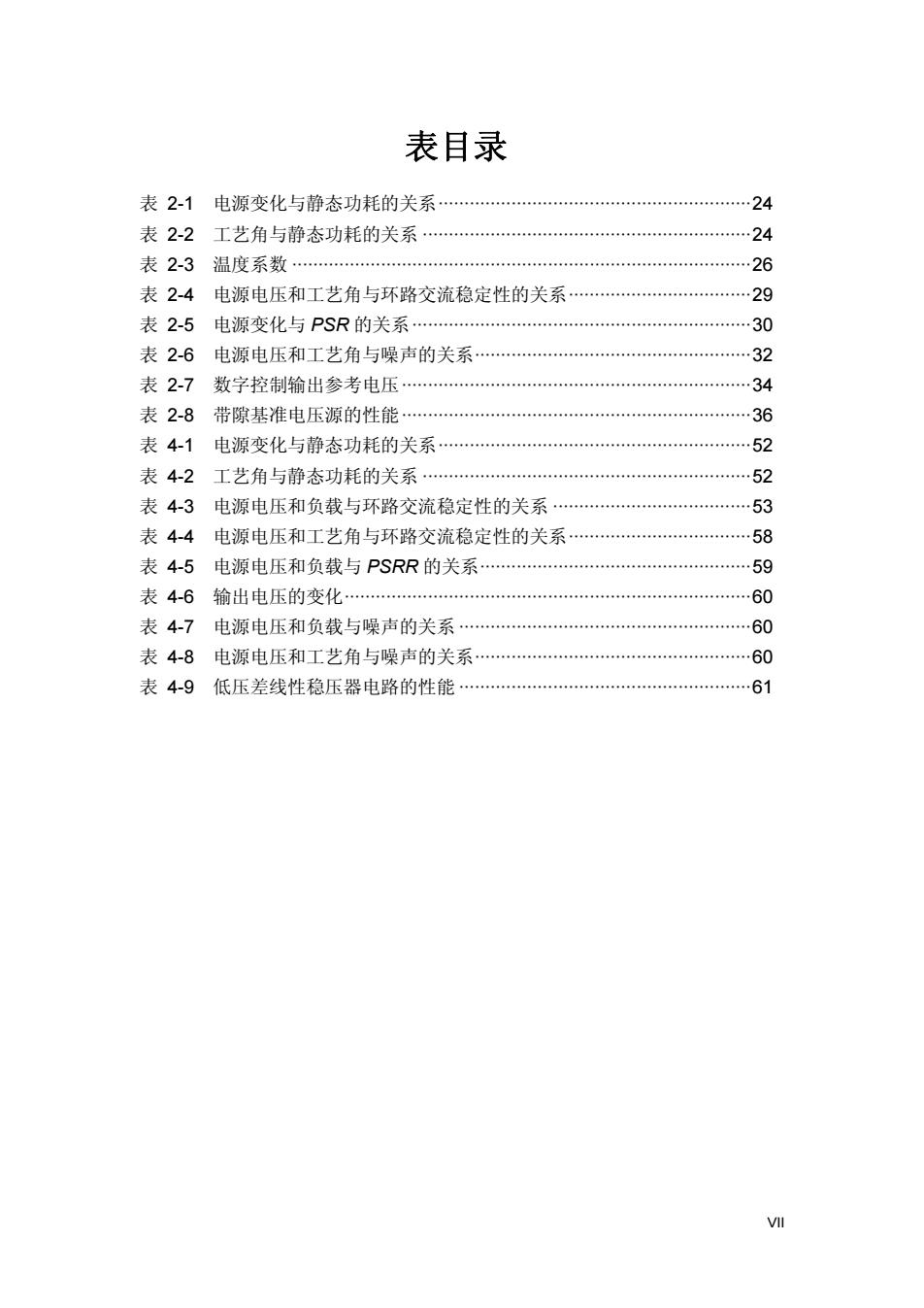
表目录 表2-1电源变化与静态功耗的关系… …24 表2-2工艺角与静态功耗的关系…24 表2-3温度系数… 26 表2-4电源电压和工艺角与环路交流稳定性的关系…29 表2-5电源变化与PSR的关系… 30 表2-6电源电压和工艺角与噪声的关系…32 表2-7数字控制输出参考电压。 34 表2-8带隙基准电压源的性能…36 表4-1电源变化与静态功耗的关系… 52 表4-2工艺角与静态功耗的关系… … 52 表4-3电源电压和负载与环路交流稳定性的关系… 53 表4-4电源电压和工艺角与环路交流稳定性的关系… … 58 表4-5电源电压和负载与PSRR的关系… 59 表4-6输出电压的变化… 60 表4-7电源电压和负载与噪声的关系…60 表4-8电源电压和工艺角与噪声的关系… 60 表4-9低压差线性稳压器电路的性能… 61 VII
VII 表目录 表 2-1 电源变化与静态功耗的关系····························································24 表 2-2 工艺角与静态功耗的关系 ·······························································24 表 2-3 温度系数 ························································································26 表 2-4 电源电压和工艺角与环路交流稳定性的关系···································29 表 2-5 电源变化与 PSR 的关系·································································30 表 2-6 电源电压和工艺角与噪声的关系·····················································32 表 2-7 数字控制输出参考电压···································································34 表 2-8 带隙基准电压源的性能···································································36 表 4-1 电源变化与静态功耗的关系····························································52 表 4-2 工艺角与静态功耗的关系 ·······························································52 表 4-3 电源电压和负载与环路交流稳定性的关系 ······································53 表 4-4 电源电压和工艺角与环路交流稳定性的关系···································58 表 4-5 电源电压和负载与 PSRR 的关系····················································59 表 4-6 输出电压的变化··············································································60 表 4-7 电源电压和负载与噪声的关系 ························································60 表 4-8 电源电压和工艺角与噪声的关系·····················································60 表 4-9 低压差线性稳压器电路的性能 ························································61

摘要 近年来由于工艺水平不断提高,电路设计技术不断进步,集成电路行业发 展迅速,应用领域不断扩展。但同时,对电路的性能要求越来越苛刻。基准源 为其他电路模块提供稳定精确的电压/电流,其性能影响电路的整体性能。 本文设计的带隙基准电压源对电源电压、工艺和温度的变化不敏感,具有高 电源电压抑制和低噪声的特点。电路中使用数字控制的PNP晶体管阵列进行软修 正。该带隙基准电压源电路能为其他电路模块提供稳定精确的电压。从仿真结果 来看,其温度系数小于28.38ppm/℃,Voo为3.3V时直流的电源抑制比为88.9 dB,Vbp为2.1V时直流的电源抑制比为65dB。从100Hz到100kHz范围的积分 噪声为13Vms。 本文设计的电压一电流转换电路使用片外可调电阻,将带隙基准电压源产生 的输出参考电压转换成稳定的电流。在电源电压和工艺的变化下其输出电流的变 化小于0.5%。 最后本文设计了低压差线性稳压器,电路的补偿结构可以使输出电压快速瞬 态响应外界负载的变化。极端条件下,相位裕度为40deg,其他条件下相位裕度 大于88deg。Vop为3.3V时直流的电源抑制比为60dB,Voo为2.1V时直流的电 源抑制比为40dB。从100Hz到100kHz范围的积分噪声为24Vms。输出电压 瞬态响应的变化小于100mV。 本文选用中芯国际的0.18-m CMOS工艺库模型进行仿真。 关键词:带隙基准电压源、低压差线性稳压器、高电源电压抑制、低噪声、软 修正、快速瞬态响应 中图分类号:TN432
1 摘 要 近年来由于工艺水平不断提高,电路设计技术不断进步,集成电路行业发 展迅速,应用领域不断扩展。但同时,对电路的性能要求越来越苛刻。基准源 为其他电路模块提供稳定精确的电压/电流,其性能影响电路的整体性能。 本文设计的带隙基准电压源对电源电压、工艺和温度的变化不敏感,具有高 电源电压抑制和低噪声的特点。电路中使用数字控制的PNP晶体管阵列进行软修 正。该带隙基准电压源电路能为其他电路模块提供稳定精确的电压。从仿真结果 来看,其温度系数小于28.38 ppm/℃,VDD为3.3 V时直流的电源抑制比为88.9 dB,VDD为2.1 V时直流的电源抑制比为65 dB。从100 Hz到100 kHz范围的积分 噪声为13 μVrms。 本文设计的电压—电流转换电路使用片外可调电阻,将带隙基准电压源产生 的输出参考电压转换成稳定的电流。在电源电压和工艺的变化下其输出电流的变 化小于0.5 ‰。 最后本文设计了低压差线性稳压器,电路的补偿结构可以使输出电压快速瞬 态响应外界负载的变化。极端条件下,相位裕度为40 deg,其他条件下相位裕度 大于88 deg。VDD为3.3 V时直流的电源抑制比为60 dB,VDD为2.1 V时直流的电 源抑制比为40 dB。从100 Hz到100 kHz范围的积分噪声为24 μVrms。输出电压 瞬态响应的变化小于100 mV。 本文选用中芯国际的0.18-μm CMOS工艺库模型进行仿真。 关键词:带隙基准电压源、低压差线性稳压器、高电源电压抑制、低噪声、软 修正、快速瞬态响应 中图分类号:TN432

Abstract In recent years,as the technology of semiconductor has improved continuously,and the circuit design technology continues to progress,the IC industry has been growing quickly,the applications continue to be widely.But at the same,that require the circuits must have higher performances. In this work,the bandgap voltage reference is insensitive with the variations of power-supply,process,and temperature,with a high power supply rejection and low noise.There is a digital control circuit to modify the number of the PNP transistor arrays,as soft-trimming.The circuit produces a stable and accurate voltage to all other integrated circuits.The simulation results are given,the temperature coefficient is less than 28.38 ppm/C.When Vop is 3.3 V the Power-Supply Rejection is 88.9 dB at DC,it is 65 dB when VDD is 2.1 V.The integrated noise from 100 Hz to 100 kHz is 13 uVrms. In this work,there is an off-chip adjustable resistance for the voltage to current converter circuit.The circuit converts the output reference voltage from the bandgap voltage reference,to a stable current.As the power supply and process vary,the variation of the output current is less than 0.5%. Finally,there is a LDO(Low Dropout Regulator)voltage regulator,the compensation scheme provides a fast transient response for output voltage as the load change.Under the extreme condition,the phase margin is 40 deg. The other conditions,phase margin are more than 88 deg.The Power-Supply Rejection is 60 dB at DC when VDD is 3.3 V,it is 40 dB when VDD is 2.1 V.The integrated noise from 100 Hz to 100 kHz is 24 uVrms.The variation of the transient response of the output is less than 100 mV. This work bases on the SMIC 0.18-um CMOS process to simulate. Keywords:Bandgap Voltage Reference,LDO,High PSRR,Low Noise, Soft-trimming,Fast Transient Response Classification Code:TN432 3
3 Abstract In recent years, as the technology of semiconductor has improved continuously, and the circuit design technology continues to progress, the IC industry has been growing quickly, the applications continue to be widely. But at the same, that require the circuits must have higher performances. In this work, the bandgap voltage reference is insensitive with the variations of power-supply, process, and temperature, with a high power supply rejection and low noise. There is a digital control circuit to modify the number of the PNP transistor arrays, as soft-trimming. The circuit produces a stable and accurate voltage to all other integrated circuits. The simulation results are given, the temperature coefficient is less than 28.38 ppm/℃. When VDD is 3.3 V the Power-Supply Rejection is 88.9 dB at DC, it is 65 dB when VDD is 2.1 V. The integrated noise from 100 Hz to 100 kHz is 13 μVrms. In this work, there is an off-chip adjustable resistance for the voltage to current converter circuit. The circuit converts the output reference voltage from the bandgap voltage reference, to a stable current. As the power supply and process vary, the variation of the output current is less than 0.5 ‰. Finally, there is a LDO(Low Dropout Regulator) voltage regulator, the compensation scheme provides a fast transient response for output voltage as the load change. Under the extreme condition, the phase margin is 40 deg. The other conditions, phase margin are more than 88 deg. The Power-Supply Rejection is 60 dB at DC when VDD is 3.3 V, it is 40 dB when VDD is 2.1 V. The integrated noise from 100 Hz to 100 kHz is 24 μVrms. The variation of the transient response of the output is less than 100 mV. This work bases on the SMIC 0.18-μm CMOS process to simulate. Keywords: Bandgap Voltage Reference,LDO,High PSRR,Low Noise, Soft-trimming,Fast Transient Response Classification Code: TN432

第一章概述 第一章概述 1.1研究动机 基准源是集成电路的重要基本单元电路,包括基准电压源和基准电流源。其 性能的好坏对整体性能影响较大。基准源除用做电源外,还为其他电路模块提供 精确的参考电压/电流。例如,将基准电压源作为运算放大器的参考输入,模数 转换器(ADC)中用于比较的标准电压等[1]。 好的稳定性是对基准源的主要要求,即对外部条件(如工作温度和电源电压 等)变化不敏感。基准的噪声和偏差都会严重地影响电路中其他模块的精度和稳 定性。因此,系统的精确度在很大程度上由基准的精度决定。基准源的性能不好, 则系统性能很难达到设计要求。 基准电压源和基准电流源并不是孤立的,电压基准可以转换为电流基准,反 之亦然。本文中电流基准源由电压基准源电路的输出参考电压转换得到。系统内 部的模块一般为电流偏置,等同于镜像基准电流,所以电流基准源必须稳定精确。 片上系统(SOC)是集成电路设计的主要趋势之一[2]。减少片外器件,减少 引脚,包含更多的子模块,减少流片、封装和测试等费用,进而降低成本。使 用线性稳压器时,其输出端的负载电流和负载电容随外接负载变化而变化,这 些变化将影响线性稳压器的稳定性,其输出电压不稳定。传统的低压差线性稳 压器需接容值较大的片外电容,使其性能稳定,可以快速响应瞬态变化。但增 加引脚意味着增加费用。无片外电容的低压差线性稳压需要增加特殊结构,用 来完成快速瞬态响应。该结构越简单越好,所需元件减少,直流功耗小:只改 善瞬态特性,不影响低压差线性稳压的直流特性。 1.2研究内容及贡献 本文设计完成了带隙基准电压源电路、电压一电流转换电路和低压差线性 稳压器电路,各部分的相互关系如图1-1所示。 带隙基准电压源电路使用数字信号控制PNP双极型晶体管数目,调整输 出参考电压,进行修正,消除温度和工艺等产生的影响。选用合适的双极型晶 体管比值和电阻的比值,可以实现低噪声的输出电压。在输出端加RC低通滤 波器滤除高频噪声,高频性能得到改善。 电压一电流转换电路使用片外可调电阻,抵消工艺产生的偏差。输出电流 支路采用低电压共源共栅结构,该结构可以增加输出阻抗,输出的偏置电流更 准确。 低压差线性稳压器的设计中增加自动检测网络,在外界负载变化较大时, 5
第一章 概述 5 第一章 概述 1.1 研究动机 基准源是集成电路的重要基本单元电路,包括基准电压源和基准电流源。其 性能的好坏对整体性能影响较大。基准源除用做电源外,还为其他电路模块提供 精确的参考电压/电流。例如,将基准电压源作为运算放大器的参考输入,模数 转换器(ADC)中用于比较的标准电压等[1]。 好的稳定性是对基准源的主要要求,即对外部条件(如工作温度和电源电压 等)变化不敏感。基准的噪声和偏差都会严重地影响电路中其他模块的精度和稳 定性。因此,系统的精确度在很大程度上由基准的精度决定。基准源的性能不好, 则系统性能很难达到设计要求。 基准电压源和基准电流源并不是孤立的,电压基准可以转换为电流基准,反 之亦然。本文中电流基准源由电压基准源电路的输出参考电压转换得到。系统内 部的模块一般为电流偏置,等同于镜像基准电流,所以电流基准源必须稳定精确。 片上系统(SOC)是集成电路设计的主要趋势之一[2]。减少片外器件,减少 引脚,包含更多的子模块,减少流片、封装和测试等费用,进而降低成本。使 用线性稳压器时,其输出端的负载电流和负载电容随外接负载变化而变化,这 些变化将影响线性稳压器的稳定性,其输出电压不稳定。传统的低压差线性稳 压器需接容值较大的片外电容,使其性能稳定,可以快速响应瞬态变化。但增 加引脚意味着增加费用。无片外电容的低压差线性稳压需要增加特殊结构,用 来完成快速瞬态响应。该结构越简单越好,所需元件减少,直流功耗小;只改 善瞬态特性,不影响低压差线性稳压的直流特性。 1.2 研究内容及贡献 本文设计完成了带隙基准电压源电路、电压—电流转换电路和低压差线性 稳压器电路,各部分的相互关系如图 1-1 所示。 带隙基准电压源电路使用数字信号控制 PNP 双极型晶体管数目,调整输 出参考电压,进行修正,消除温度和工艺等产生的影响。选用合适的双极型晶 体管比值和电阻的比值,可以实现低噪声的输出电压。在输出端加 RC 低通滤 波器滤除高频噪声,高频性能得到改善。 电压—电流转换电路使用片外可调电阻,抵消工艺产生的偏差。输出电流 支路采用低电压共源共栅结构,该结构可以增加输出阻抗,输出的偏置电流更 准确。 低压差线性稳压器的设计中增加自动检测网络,在外界负载变化较大时