电路学习指导 第三章电阻电路的一般分析 CAPTER 7 SINUSOIDAL STEADY-STATE ANALYSIS 7-1 Introduction In chapter 9, we have learned how to apply Ohm's and Kirchhoff's laws to AC circuit. In this chapter, we want to see how nodal analysis, mesh analysis, Thevenin's theorem, Norton's theorem, superposition, and source transformations are applied in analyzing AC In this chapter we will discuss the analysis method, resonance and ac power analysis 7-2 Steps to analyze AC circuits 1 transform the circuit to phasor or frequency domain 2 solve the problem using circuit techniques (nodal analysis, mesh analysis, superposition,etc.) 3 transform the result phasor into time domain(required) X(w) col. 7-3Series ResonanceThe series R X(w) and C along with resistance jool. R is shown as Fig.7-1 U / The impedance is 0 Z=R+(L-) As wincrease, Z decrease, as w continue to increase, a point is reached where the reactance term is zero shown as Fig.7-2. When Do=VIC the circuit is resonant, we call it a series resonance or current resonance. Because in this condition,the current is maximum. The characteristic impedance and quality-factor are defined as 0am nono -or U8 R1 -mas.i- UR/U Q1<R2<R3 0 =-18 1 --100.P=Rr. 0.707 Q1 The phasor diagram is shown as Fig.7-3. Because Q2 Q3 0 1:y= 21
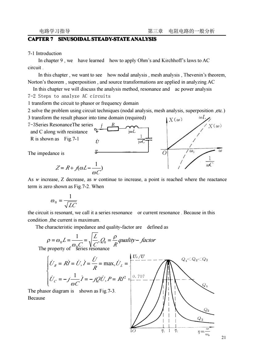
电路学习指导 第三章 电阻电路的一般分析 21 CAPTER 7 SINUSOIDAL SINUSOIDAL SINUSOIDAL SINUSOIDAL STEADY-STATE STEADY-STATE STEADY-STATE STEADY-STATE ANALYSIS ANALYSIS ANALYSIS ANALYSIS 7-1 Introduction In chapter 9 , we have learned how to apply Ohm’s and Kirchhoff’s laws to AC circuit . In this chapter , we want to see how nodal analysis , mesh analysis , Thevenin’s theorem, Norton’s theorem , superposition , and source transformations are applied in analyzing AC In this chapter we will discuss the analysis method, resonance and ac power analysis 7-2 Steps to analyze AC circuits 1 transform the circuit to phasor or frequency domain 2 solve the problem using circuit techniques (nodal analysis, mesh analysis, superposition ,etc.) 3 transform the result phasor into time domain (required) 7-3Series ResonanceThe series arrangement of L and C along with resistance R is shown as Fig.7-1 Fig.7-1 The impedance is Fig.7-2 As w increase, Z decrease, as w continue to increase, a point is reached where the reactance term is zero shown as Fig.7-2. When the circuit is resonant, we call it a series resonance or current resonance . Because in this condition ,the current is maximum. The characteristic impedance and quality-factor are defined as The property of series resonance The phasor diagram is shown as Fig.7-3. Because ) 1 ( C Z R j L ω = + ω − LC 1 ω 0 = quality factor R Q C L C = L = = = − ρ ω ρ ω 0 0 0 , 1 ⎪ ⎪ ⎩ ⎪⎪ ⎨ ⎧ = − = − = = = = = = = = , max 1 , max, 2 0 I jQU P RI C U j U j LI jQU R U U RI U I C R L ̇ ̇ ̇ ̇ ̇ ̇ ̇ ̇ ̇ ̇ ̇ ω ω
电路学习指导 第三章电阻电路的一般分析 2o)= OL 1 U,=RI-RZo II →Ue/U=1/V1+☑(-1/n)2 the resonant curve is shown as Fig.7-4 Fig.7-4 Fig.7-3 The higher the value ofQ,the more selective the circuit is but the smaller the bandwith BW=Q/f0 when Q>>1. 7-4 Parallel Resonance The parallel RLC circuit is the dual of the series RLC circuit shown as Fig.7-5.Admittance is Resonance occurs when the imaginary part of Y is zero.The frequency quality factor and 0。= 元awr 0=0C 1 LG 1=-j0I,=-1 7-5 The instantaneous power p(t)absorbed by an element is the product of the instantan-eous voltage u(t)across the element and the current i(t)through it.Suppose un)=U2 cos(@r+) The instantanebs pouecgs(+) This show)batheins8su36gasM件pp平9,)The first part is constant.Its value depends on the phase difference between the voltage and current.The second part is a sinusoidal function whose fre-quency is2 which is twice the angular frequency of the voltage or current shown as Fig.7 12
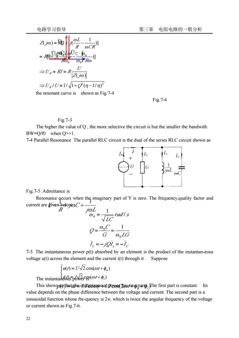
电路学习指导 第三章 电阻电路的一般分析 22 the resonant curve is shown as Fig.7-4 Fig.7-4 Fig.7-3 The higher the value of Q , the more selective the circuit is but the smaller the bandwith. BW=Q/f0 when Q>>1. 7-4 Parallel Resonance The parallel RLC circuit is the dual of the series RLC circuit shown as Fig.7-5. Admittance is Resonance occurs when the imaginary part of Y is zero. The frequency,quality factor and current are given below: 7-5 The instantaneous power p(t) absorbed by an element is the product of the instantan-eous voltage u(t) across the element and the current i(t) through it . Suppose The instantaneous power is This shows us that the instantaneous power has two parts. The first part is constant. Its value depends on the phase difference between the voltage and current. The second part is a sinusoidal function whose fre-quency is 2w, which is twice the angular frequency of the voltage or current shown as Fig.7-6. 2 2 0 0 0 0 / 1/ 1 ( 1/ ) ( ) [1 ( )] )] 1 ( ) [1 ( η η ω ω ω ω ω ω ω ω ω ω ⇒ = + − ⇒ = = = + − = + − U U Q Z j U U RI R R CR L R j R CR L Z j R j R R j L j C R Y ω ω 1 1 = + + L s C I jQI I G LG C Q rad s LC ̇ = − ̇ = − ̇ = = = 0 0 0 1 / 1 ω ω ω ⎪ ⎩ ⎪ ⎨ ⎧ = + = + ( ) 2 cos( ) ( ) 2 cos( ) iu i t I t u t U t ω φ ω φ ( ) cos cos(2 ) u i p t = ui =UI ϕ +UI ωt +φ +φ
电路学习指导 第三章电阻电路的一般分析 Average powerThus ndU7c0s-Re(7) P=RP P=0=P 9=0.-0 Power Apparent Power Power Factor and Complex Powe Consider the circuit(shown as Fig.7-7)and suppose the impedance are Zo Ry +ir Z=R+iX Ns S=U,m吃P P nd 3=m=P+0 r=百6aR,Z=,hsPm=U公 So the average power isApparent power,power factor,complex power,reactive (qua-drature)power are respectivelyTheir relationship are shown as Fig.7-8 Fig.7-8 7-7 Power Factor CorrectionMost domestic loads(washing machine,air conditioners, refrigerators)and industrial loads(motors)are inductive and operate at a low lagging power factor(i lag u).Although the inductive nature of the load cannot be changed,we can increase its pf.The process of increasing the pf without altering the voltage or cur-rent to the original load is known as pf correction.A inductive load's pf is corrected by deliberately installing a capacitor in parallel with the load as in the circuit shown as Fig.79 1i2) 23
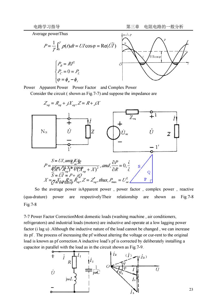
电路学习指导 第三章 电阻电路的一般分析 23 Average powerThus Fig.7-67-6 Maximum Power Apparent Power Power Factor and Complex Power Consider the circuit ( shown as Fig.7-7) and suppose the impedance are Fig.7-7 So the average power isApparent power , power factor , complex power , reactive (qua-drature) power are respectivelyTheir relationship are shown as Fig.7-8 Fig.7-8 7-7 Power Factor CorrectionMost domestic loads (washing machine , air conditioners, refrigerators) and industrial loads (motors) are inductive and operate at a low lagging power factor (i lag u) .Although the inductive nature of the load cannot be changed , we can increase its pf . The process of increasing the pf without altering the voltage or cur-rent to the original load is known as pf correction.A inductive load’s pf is corrected by deliberately installing a capacitor in parallel with the load as in the circuit shown as Fig.7-9. ) ~ ( ) cos Re( 1 0 p t dt UI UI T P T = = = ̇ ∫ ϕ ⎪ ⎩ ⎪ ⎨ ⎧ = − = = = u i C L R P P P RI ϕ φ φ 0 2 Zeq = Req + jX eq , Z = R + jX , , 0, 0 ( ) ( ) 2 2 2 = ∂ ∂ = ∂ ∂ + + + = X P R P and R R X X U R P eq eq oc eq eq eq P Uoc Req X X , R R ,Z Z ,thus, / 4 2 max * = − = = = ϕ ϕ sin ~ ~ / cos , , Q UI S UI P jQ pf P S S UI unit VA = = = + = = = ̇
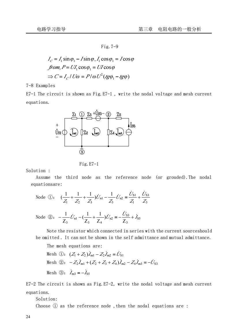
电路学习指导 第三章电阻电路的一般分析 Fig.7-9 =/sino-/sino,/coso /coso from,P=Ul cos =Ulcosp C=IclUo PloU-(igo-igo) 7-8 Examples E7-1 The circuit is shown as Fig.E7-1,write the nodal voltage and mesh current equations. 凸0®5 + iΦ©1e@ ③ Fig.E7-1 Solution: Assume the third node as the reference node (or grouded).The nodal equationsare: 咖@:方+云 ☑2 Note the resistor which connected in series with the current sourceshould be omitted.It can not be shown in the self admittance and mutual admittance. The mesh equations are: Mesh①:(☑+Z)ial-Zim=ii Mesh②:-Z3lnml+(Z+☑+Z)1m2-Zams=-U3 Mesh③:/m=-lss E7-2 The circuit is shown as Fig.E7-2,write the nodal voltage and mesh current equations. Solution: Choose D as the reference node,then the nodal equations are 24
电路学习指导 第三章 电阻电路的一般分析 24 Fig.7-9 7-8 Examples E7-1 The circuit is shown as Fig.E7-1 , write the nodal voltage and mesh current equations. Fig.E7-1 Solution : Assume the third node as the reference node (or grouded).The nodal equationsare: Node ①: 1 ) 1 1 1 ( 3 S3 1 S1 n2 3 n1 1 2 3 Z U Z U U Z U Z Z Z ̇ ̇ + + ̇ − ̇ = + Node ②: S5 3 S3 n2 3 4 n1 3 Z ) Z 1 Z 1 ( Z 1 I U U U ̇ ̇ − ̇ − + ̇ = − + Note the resistor which connected in series with the current sourceshould be omitted . It can not be shown in the self admittance and mutual admittance. The mesh equations are: Mesh ①: (Z1 Z2 )I m1 Z2 I m2 US1 + ̇ − ̇ = ̇ Mesh ②: Z2 I m1 (Z2 Z3 Z4 )I m2 Z4 I m3 US3 − ̇ + + + ̇ − ̇ = − ̇ Mesh ③: I m3 IS5 ̇ ̇ = − E7-2 The circuit is shown as Fig.E7-2, write the nodal voltage and mesh current equations. Solution: Choose ① as the reference node ,then the nodal equations are : / / ( ) , cos cos sin sin , cos cos 1 2 1 1 1 1 1 1 ω ω ϕ ϕ ϕ ϕ ϕ ϕ ϕ ϕ C I U P U tg tg from P UI UI I I I I I C C ⇒ = = − = = = − =
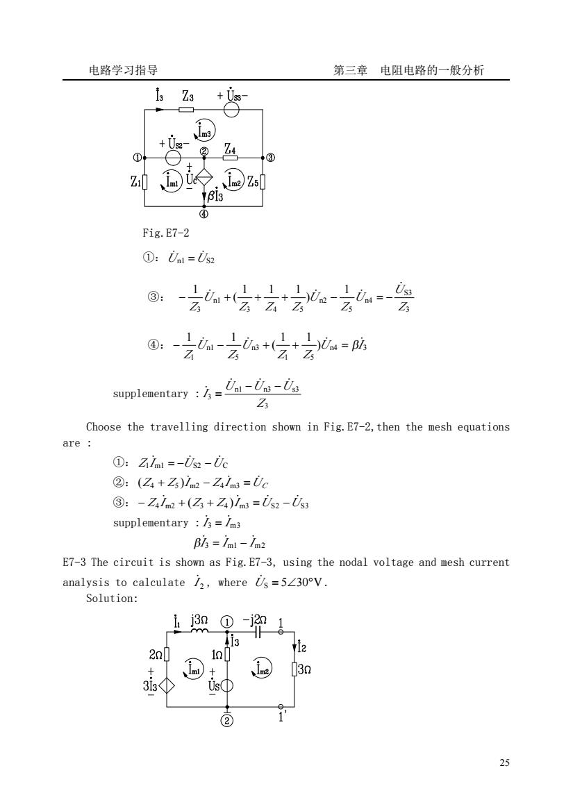
电路学习指导 第三章电阻电路的一般分析 +0e ②Z4 +③ ④ Fig.E7-2 ①:Unl=i supplementarya-U Z Choose the travelling direction shown in Fig.E7-2,then the mesh equations are ①:Zim=-02-0c ②:(Z+Z)lm-Zm=Uc ③:-Zim+(Z+Za)lm=i2-i3 supplementary /3=/m3 Bls=/ml-72 E7-3 The circuit is shown as Fig.E7-3,using the nodal voltage and mesh curren analysis to calculate/,where=5∠30V Solution: 3 2n0 13m ② 25
电路学习指导 第三章 电阻电路的一般分析 25 Fig.E7-2 ①:Un1 US2 ̇ ̇ = ③: 3 S3 n4 5 n2 3 4 5 n1 3 1 ) 1 1 1 ( 1 Z U U Z U Z Z Z U Z ̇ − ̇ + + + ̇ − ̇ = − ④: n4 3 1 5 n3 5 n1 1 ) 1 1 ( 1 1 U I Z Z U Z U Z − ̇ − ̇ + + ̇ = β̇ supplementary : 3 n1 n3 s3 3 Z U U U I ̇ ̇ ̇ ̇ − − = Choose the travelling direction shown in Fig.E7-2,then the mesh equations are : ①: Z1I m1 US2 UC ̇ = − ̇ − ̇ ②: Z Z I Z I UC + ̇ − ̇ = ̇ ( 4 5 ) m2 4 m3 ③: Z4 I m2 (Z3 Z4 )I m3 US2 US3 − ̇ + + ̇ = ̇ − ̇ supplementary : I 3 I m3 ̇ = ̇ I 3 I m1 I m2 β̇ = ̇ − ̇ E7-3 The circuit is shown as Fig.E7-3, using the nodal voltage and mesh current analysis to calculate 2 I ̇ , where U̇S = 5∠30°V . Solution: