电路学习指导 第三章电阻电路的一般分析 CAPTER6 SINUSOIDSAND PHASORS 6-1 Introduction We now begin the analysis of circuit in which the source voltage or current is time varying. In this chapter we are particularly interested in sinusoidally time-varying excitation, or simply, excitation by a sinusoid. It is the sinusoid steady-state response that is main interest to us in this chapter. A sinusoid is a signal that has the form of the sine or cosine function. Alternating current reverses at regular time intervals and has alternatively positive and negative values. Circuit driven by sinusoidal current or voltage sources are called ac circuit. We begin with a basic discussion of sinusoids, effective value and phasors, then introduce the concepts of impedance and admittance and their connections. The basic circuit laws, Kirchoff's and Ohm's law, introduced in de (direct current ) circuit, will be applied to ac circuit. 6-2 Sinusoids Consider the sinusoidal voltage u(1)=Umcos(1+φ) Where Um=the amplitude of the sinusoid, w=the angular frequency in radians /s. o+ is the argument of the siusoid.When tex iti s allete initial phase-In is the period of the sinusoid. The frequency is f=1/T, and w=2*pi*f. The sinusoid is shown as Fig 6-1 U u m 2元 0 —# π 2元 wl To u=Umcos(1+φn) i=Imcos(o1+φ) p=u-o,is the phase difference,when does not equal to 0,we say /and ware out of phase; otherwise, we say they are in phase. Also, when it is great than 0, we say leads / by o,when it is less than O,we say u lagsiby o.when it is 180 or-180 degree,we say u and i are in inverse phase, and when it is 90 or-90 degree, we say u and i are vertical. Keep in mind -丌≤,,甲≤丌 21
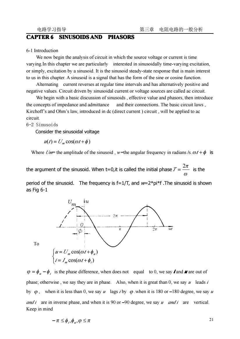
电路学习指导 第三章 电阻电路的一般分析 21 CAPTER 6 SINUSOIDS SINUSOIDS SINUSOIDS SINUSOIDS AND PHASORS PHASORS PHASORS PHASORS 6-1 Introduction We now begin the analysis of circuit in which the source voltage or current is time varying.In this chapter we are particularly interested in sinusoidally time-varying excitation, or simply, excitation by a sinusoid. It is the sinusoid steady-state response that is main interest to us in this chapter. A sinusoid is a signal that has the form of the sine or cosine function. Alternating current reverses at regular time intervals and has alternatively positive and negative values. Circuit driven by sinusoidal current or voltage sources are called ac circuit. We begin with a basic discussion of sinusoids , effective value and phasors, then introduce the concepts of impedance and admittance and their connections. The basic circuit laws , Kirchoff’s and Ohm’s law, introduced in dc (direct current ) circuit , will be applied to ac circuit. 6-2 Sinusoids Consider the sinusoidal voltage Where Um= the amplitude of the sinusoid , w=the angular frequency in radians /s.ωt +φ is the argument of the sinusoid. When t=0,it is called the initial phase ω 2π T = is the period of the sinusoid. The frequency is f=1/T, and w=2*pi*f .The sinusoid is shown as Fig 6-1 Fig.6-1 To ϕ = φ u −φ i is the phase difference, when does not equal to 0, we say i and u are out of phase; otherwise , we say they are in phase. Also, when it is great than 0, we say u leads i by ϕ , when it is less than 0, we say u lags i by ϕ .when it is 180 or –180 degree, we say u and i are in inverse phase, and when it is 90 or –90 degree, we say u and i are vertical. Keep in mind u(t) =U cos(ωt +φ ) m ⎩ ⎨ ⎧ = + = + cos( ) cos( ) m i m u i I t u U t ω φ ω φ −π ≤ φi,φu ,ϕ ≤ π
电路学习指导 第三章电阻电路的一般分析 A direct source applied to the resistor R in a period causes the energy is While a alterating current through the same resistor in a period causes the energy is Tf they are equal,I is called the effective value ofi 75 1= 6-4 Complex number 1 Rectangular form 法m✉ 个+ =rZ=e 中■ Wherer is the magnitude is the phase or angle. =行些玩,产与得张) x=rcoso,y=rsind ∴.z=cosp+/sino), triangleform Complex number operations Addition and subtractionParallelogram Triangle 以边运电 MultiplicationSquare root E=F∠A Reciprocal
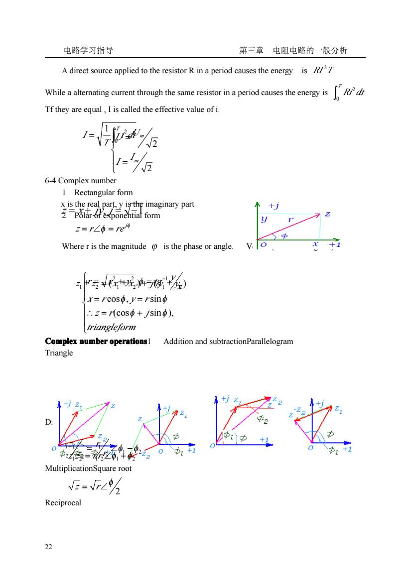
电路学习指导 第三章 电阻电路的一般分析 22 A direct source applied to the resistor R in a period causes the energy is RI T 2 While a alternating current through the same resistor in a period causes the energy is ∫ T Ri dt 0 2 Tf they are equal , I is called the effective value of i. 6-4 Complex number 1 Rectangular form x is the real part, y is the imaginary part 2 Polar or exponential form Where r is the magnitude ϕ is the phase or angle. Vector (shown as Fig.6-2) Complex Complex Complex Complex number operations operations operations operations1 Addition and subtractionParallelogram Triangle Fig.6-3 Fig.6-4 Division MultiplicationSquare root Reciprocal ∫ = T i dt T I 0 1 2 ⎪ ⎩ ⎪ ⎨ ⎧ = = 2 2 m m I I U U z = x + jy, j = −1 φ φ j z = r∠ = re ( ) ( ) 1 2 1 2 1 2 z ± z = x ± x + j y ± y 1 2 2 1 2 1 = ∠φ −φ r r z z 1 2 = 1 2∠φ1 +φ2 z z rr 2 φ z = r∠ ⎪ ⎪ ⎩ ⎪ ⎪ ⎨ ⎧ ∴ = + = = = + = − triangleform z r j x r y r x y r x y tg (cos sin ), cos , sin , 2 2 1 φ φ φ φ φ
电路学习指导 第三章电阻电路的一般分析 养步62-Rmi=Raw5 Complex conjugateBecause 从1 li=Rel2u] or or the sinor is Its i proj Fig.6-5 Fig.6-6 Thus,whenever a sinusoid is expressed as a phasor,the termis implicitly prescent.So. when we dealing with phasors,to keep in mind the frequencyof the phasor.The graphical representation of phasor is known as a phasor diagram.Shown as:Note that the phasor not explicitly shows thebecause is a constant.However the response dependsonEor this reason,the phasor domain is also known as the frequency domain We should keep in mind that phasor analysis applies only when frequency is constant;it applies in manipulating two or more sinusoidal signals only if they are of the same frequency. Phasor Relationship for Circuit Elements and Kirchhoffs Lawsreason R + u U Fig 6-7Its phasor diagram is shown as Fig6-10 a. =-@L/sin(@/+6) =oL/cos(++90) .0=oL1∠中+90°=oLi L i 三 u Fig.6-8Its phasor diagram is shown as Fig.6-10 b. =-@CUsin+) =OCUcost+6+90) ∴1=0CL0+90=0CU ori=-111
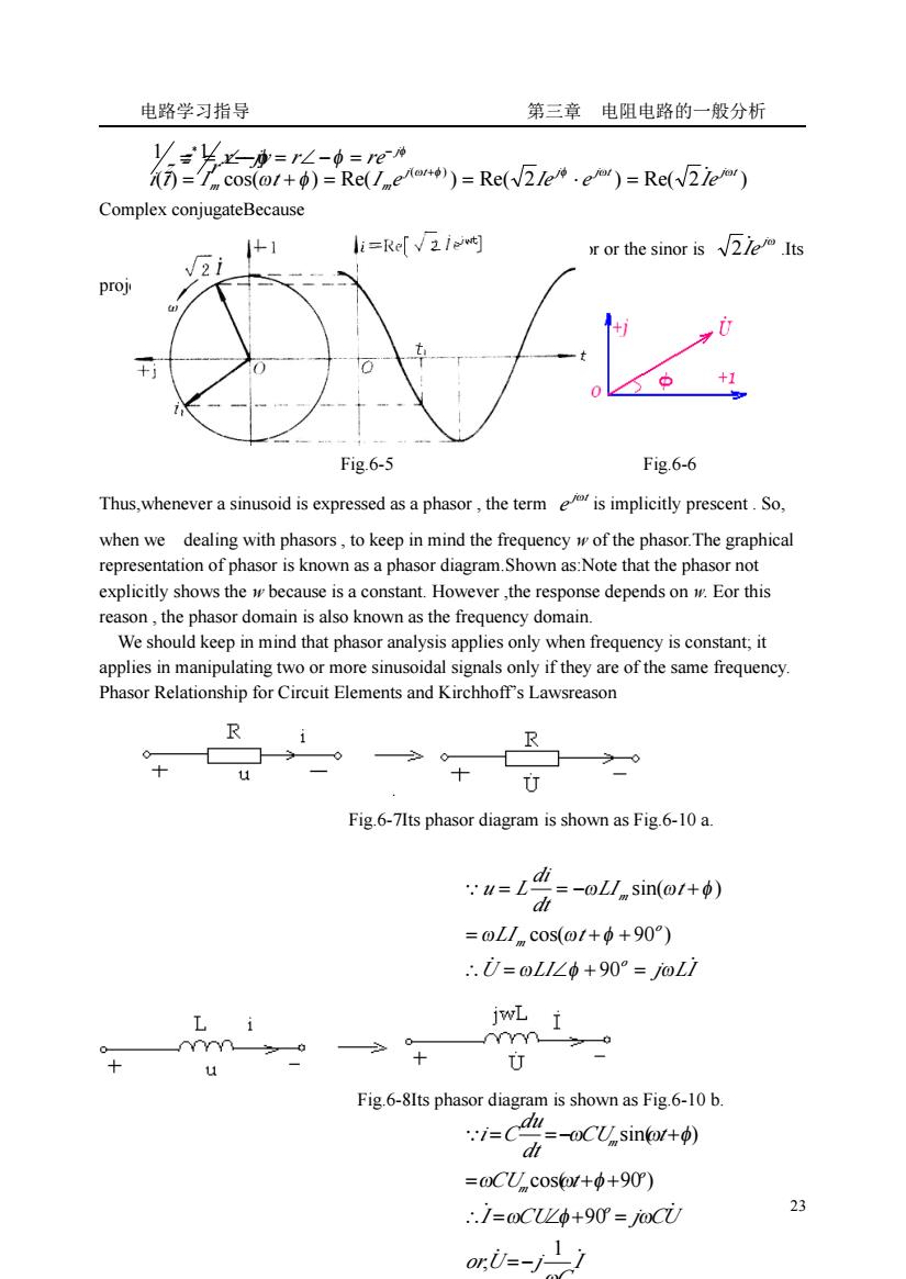
电路学习指导 第三章 电阻电路的一般分析 23 Complex conjugateBecause φ φ I = Ie = I∠ j ̇ is the representation of i(t),The rotate phasor or the sinor is jω Iė 2 .Its projection on the real axis is i(t) Fig.6-5 Fig.6-6 Thus,whenever a sinusoid is expressed as a phasor , the term j t e ω is implicitly prescent . So, when we dealing with phasors , to keep in mind the frequency w of the phasor.The graphical representation of phasor is known as a phasor diagram.Shown as:Note that the phasor not explicitly shows the w because is a constant. However ,the response depends on w. Eor this reason , the phasor domain is also known as the frequency domain. We should keep in mind that phasor analysis applies only when frequency is constant; it applies in manipulating two or more sinusoidal signals only if they are of the same frequency. Phasor Relationship for Circuit Elements and Kirchhoff’s Lawsreason Fig.6-7Its phasor diagram is shown as Fig.6-10 a. Fig.6-8Its phasor diagram is shown as Fig.6-10 b. = ∠−φ z r 1 1 φ φ j z x jy r re − = − = ∠− = * ( ) cos( ) Re( ) Re( 2 ) Re( 2 ) j( t ) j j t j t m m i t I t I e Ie e Ie ω φ φ ω ω ω φ = ̇ = + = = ⋅ + U LI j LI LI t LI t dt di u L o o m m ̇ ̇ ∵ ω φ ω ω ω φ ω ω φ ∴ = ∠ + = = + + = = − + 90 cos( 90 ) sin( ) I C orU j I CU j CU CU t CU t dt du i C o o m m ̇ ̇ ̇ ̇ ∵ ω ω φ ω ω ω φ ω ω φ 1 , 90 cos( 90 ) sin( ) =− ∴ = ∠ + = = + + = =− +
电路学习指导 第三章电阻电路的一般分析 wC i 0 H 11 Fig.6-9 Its phasor diagram is shown as Fig.6-10 c. m 刀 i a 电型 Fig.6-10 6-7 Impedance and Admittance Ohm's law in phasor form for any type ofelement as Where Z=ili.or.i=zt Z is a frequency dependent quantity known as impedance,measured in ohms.Although the impedance is the ratio of two phasors,it is not a phasor,because it does not correspond to a Z=R+X=∠0,A=√R+r,0=g'R=cos0,r=sin0 sinusoidally varying quantity.And: Call X reactance,=oL inductive reactance =l/Ccapacitive reactance, and=-c.0 impedance angle,the magnitude.The impedance triangle is shown as Fig.6-11 Fig.6-11 12 :.x<0.capacite 0=0,(p。-p,)=0,r=0,resistive R [p>0,(p.-p,)<0,B>0:8<0,r<0,capacitive {p<0,(φ,-p,)>0,B<0:0>0,r>0,inductive p=0,(pn-p,)=0,B=0,0=0,r=0,resistive The admittance is defined asB is called susceptance BC capacitive susceptance.BL inductive susceptance
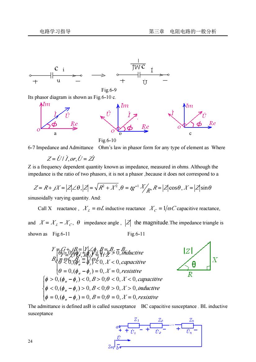
电路学习指导 第三章 电阻电路的一般分析 24 Fig.6-9 Its phasor diagram is shown as Fig.6-10 c. a b c Fig.6-10 6-7 Impedance and Admittance Ohm’s law in phasor form for any type of element as Where Z is a frequency dependent quantity known as impedance, measured in ohms. Although the impedance is the ratio of two phasors, it is not a phasor ,because it does not correspond to a sinusoidally varying quantity. And: Call X reactance , X L = ωL inductive reactance X C = 1 ωC capacitive reactance, and X = X L − X C , θ impedance angle , Z the magnitude.The impedance triangle is shown as Fig.6-11 Fig.6-11 The admittance is defined asB is called susceptance BC capacitive susceptance . BL inductive susceptance Z U I or U ZI = ̇ ̇ ̇ = ̇ / , , θ , ,θ , cosθ, sinθ 2 2 1 R Z X Z R Z = R + jX = Z ∠ Z = R + X = tg X = = − ⎪ ⎩ ⎪ ⎨ ⎧ = − = = < − < < > − > > X resistive X capacitive X inductive u i u i u i 0,( ) 0, 0, 0,( ) 0, 0, 0,( ) 0, 0, θ φ φ θ φ φ θ φ φ Y = I ̇ /U̇ ,so,Y =1/ Z B C B L Y G jB Y B B B C L L C ω ω φ , 1/ , = = = + = ∠ = − ⎪ ⎩ ⎪ ⎨ ⎧ = − = = = = < − > < > > > − < > < < B X resistive B X inductive B X capacitive u i u i u i 0,( ) 0, 0; 0, 0, 0,( ) 0, 0; 0, 0, 0,( ) 0, 0; 0, 0, φ φ φ θ φ φ φ θ φ φ φ θ
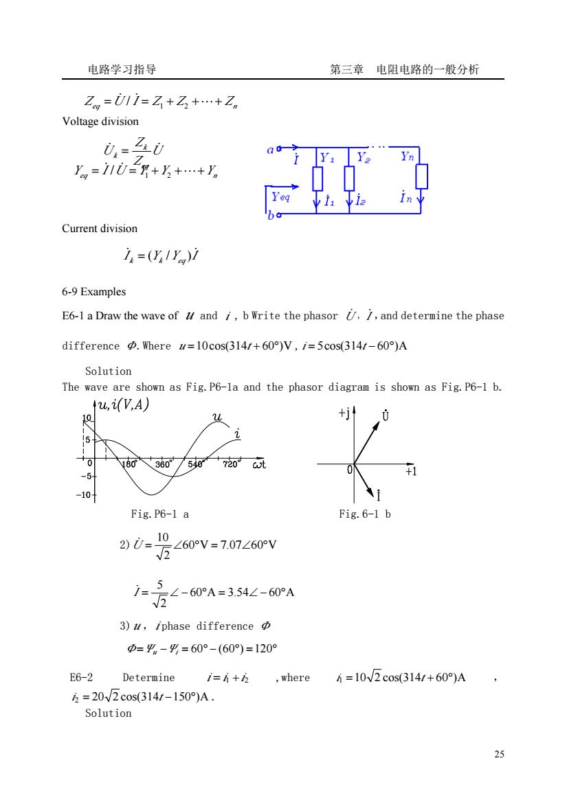
电路学习指导 第三章电阻电路的一般分析 Z=011=Z+Z3+.+Z。 Voltage division 0-三d Y. Yn =11U=月+乃+.+ Current division i=(y1y)1 6-9 Examples E6-1 a Draw the wave of and i,b Write the phasor /and determine the phase difference Where w=10cos(314/+60)V,/=5cos(314/-60)A Solution The wave are shown as Fig.P6-la and the phasor diagram is shown as Fig.P6-1 b. ,(V,A) 10 1 036o/50+720 +1 -5 10 Fig.P6-1 a Fig.6-1 b <60V=707∠60V 2)0=-10 万-60A=3.54∠-60A 3)u,iphase difference =平-g=60°-(60)=120° E6-2 Determine i=i+乃 where =10W2c0s(3141+60)A 5=20√2cos(314/-150°)A. Solution 25
电路学习指导 第三章 电阻电路的一般分析 25 Voltage division Current division 6-9 Examples E6-1 a Draw the wave of u and i , b Write the phasor U̇ , I ̇ ,and determine the phase difference Φ.Where u =10cos(314t + 60°)V , i = 5cos(314t − 60°)A Solution The wave are shown as Fig.P6-1a and the phasor diagram is shown as Fig.P6-1 b. Fig.P6-1 a Fig.6-1 b 2) 60 V 7.07 60 V 2 10 U = ∠ ° = ∠ ° ̇ 60 A 3.54 60 A 2 5 I = ∠ − ° = ∠ − ° ̇ 3) u ,i phase difference Φ Φ=Ψu −Ψi = 60° − (60°) =120° E6-2 Determine i = i1 + i2 ,where i1 =10 2 cos(314t + 60°)A , i2 = 20 2 cos(314t −150°)A . Solution eq Z Z Zn Z =U̇ / I ̇ = 1 + 2 +⋯+ U Z Z U eq k k ̇ = ̇ eq U Y Y Yn Y = I ̇ / ̇ = 1 + 2 +⋯+ I Y Y I k k eq ̇ ̇ = ( / )