电路学习指导 第三章电阻电路的一般分析 CAPTER4 CIRCUIT THEOREMS 4-1 Linearity Property Linearity is the property of an element describing a linear relationship between cause and effect. The homogeneity property requires that if the input( excitation ) is multiplied by a constant, then the output( response )is multiplied by the same constant. The additivity property requires that the response to a sum of inputs is the sum of the responses to each input applied separately. A circuit element is a linear element if the voltage-current relationship satisfies both the homogeneity and additivity properties. In general, a circuit is linear if it is both the homogeneous and additive. A linear circuit consists only linear elements, linear dependent and independent sources. A linear circuit is one whose output is linearly related(directly proportional)to its input 4-2 Superposition If a circuit has two or more independent sources, one way to determine the value of a specific variable(voltage or current)is to use nodal or mesh analysis as in Chapte 3. Another way is to etermine the contribution of each independent source to the variable and then add them up. The later approach is known as the superposition. The superposition principle states that the voltage across(or current through) an element in a linear circuits is the algebraic sum of the voltage across(or current through) that element due to each independent source acting alone. 2. Dependent sources are left intact because they are controlled by other circuit variables. 3.Can not use superposition to determine power, because P=UI,it is not a linear variable. 4-3 Thevenin's Theorem It often occurs in practice that a particular element in a circuit is variable(load)while other elements are fixed. Each time the variable element is changed, the entire circuit has to be analyzed all over again. To avoid this problem, Thevenin's theorem provides a technique by which the fixed part of the circuit is replaced by an equivalent circuit Thevenin's theorem states that a active linear two-terminal circuit can be replaced by an equivalent circuit consisting of a voltage source Uth in series with a resister Rth.shown as Fig.4-1 Where Uth is the open-circuit voltage Uoc at the terminals(shown as Fig.4-2 a). Rth is the input or equivalent resistance Reg at the terminals when the independent sources are turned off (shown as Fig.4-2 b). To calculate Reg, we need to consider two cases: Case one: If NO has no controlled sources, Reg is the input or equivalent resistance looking between terminal a and b. Case two: If the NO has the controlled 21
电路学习指导 第三章 电阻电路的一般分析 21 CAPTER 4 CIRCUIT CIRCUIT CIRCUIT CIRCUIT THEOREMS THEOREMS THEOREMS THEOREMS 4-1 Linearity Property Linearity is the property of an element describing a linear relationship between cause and effect. The homogeneity property requires that if the input ( excitation ) is multiplied by a constant , then the output ( response ) is multiplied by the same constant . The additivity property requires that the response to a sum of inputs is the sum of the responses to each input applied separately. A circuit element is a linear element if the voltage-current relationship satisfies both the homogeneity and additivity properties. In general, a circuit is linear if it is both the homogeneous and additive . A linear circuit consists only linear elements , linear dependent and independent sources. A linear circuit is one whose output is linearly related ( directly proportional ) to its input. 4-2 Superposition If a circuit has two or more independent sources, one way to determine the value of a specific variable (voltage or current ) is to use nodal or mesh analysis as in Chapte 3. Another way is to determine the contribution of each independent source to the variable and then add them up. The later approach is known as the superposition. The superposition principle states that the voltage across (or current through) an element in a linear circuits is the algebraic sum of the voltage across (or current through) that element due to each independent source acting alone. 2. Dependent sources are left intact because they are controlled by other circuit variables. 3.Can not use superposition to determine power, because P=UI ,it is not a linear variable. 4-3 Thevenin’s Theorem It often occurs in practice that a particular element in a circuit is variable (load ) while other elements are fixed .Each time the variable element is changed , the entire circuit has to be analyzed all over again. To avoid this problem , Thevenin’s theorem provides a technique by which the fixed part of the circuit is replaced by an equivalent circuit. Thevenin’s theorem states that a active linear two-terminal circuit can be replaced by an equivalent circuit consisting of a voltage source Uth in series with a resister Rth .shown as Fig.4-1 Where Uth is the open-circuit voltage Uoc at the terminals(shown as Fig.4-2 a). Rth is the input or equivalent resistance Req at the terminals when the independent sources are turned off (shown as Fig.4-2 b).To calculate Req ,we need to consider two cases: Case one : If N0 has no controlled sources , Req is the input or equivalent resistance looking between terminal a and b. Case two:If the N0 has the controlled
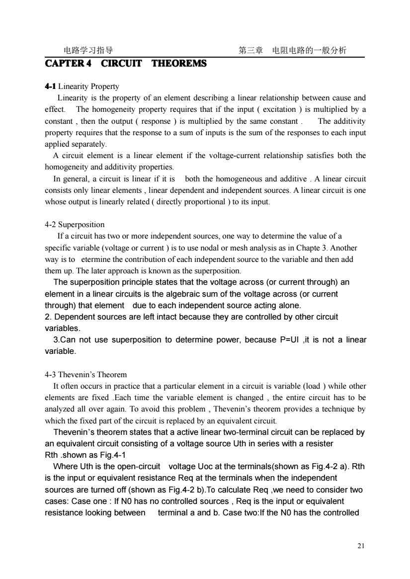
电路学习指导 第三章电阻电路的一般分析 sources,we apply a voltage source u at the terminals and determine the resulting i, so Reg=w/i.(shown as Fig.4-2 c). linear Rth two-port with )Uth scources be replaced by Fig.4-1 linear linear linear 十 two-port two-port two-port with Uth without without scources 6 scources bRth scources a b Fig.4-2 4-4 Norton's Theorem Norton's theorem states that a active linear two-terminal circuit can be replaced by an equivalent circuit consisting of a current source iN in parallel with a resister RN(shown as Fig.4-3) Where iN is the short-circuit current isc at the terminals(shown as Fig.4-4 a).RN is the input or equivalent resistance Req at the terminals when the independent sources are turned off. To calculate Reg ,we need to consider two cases:Case one:If NO has no controlled sources.Rea is the input or equivalent resistance lookina between terminal a and b(shown as Fig.4-4 b).Case two:lf the NO has the controlled sources we apply a voltage source u at the terminals and determine the resulting I,so Req=u/ i.(shown as Fig.4-4 linear two-port IN with RN scources be replaced by Fig.4-3 22
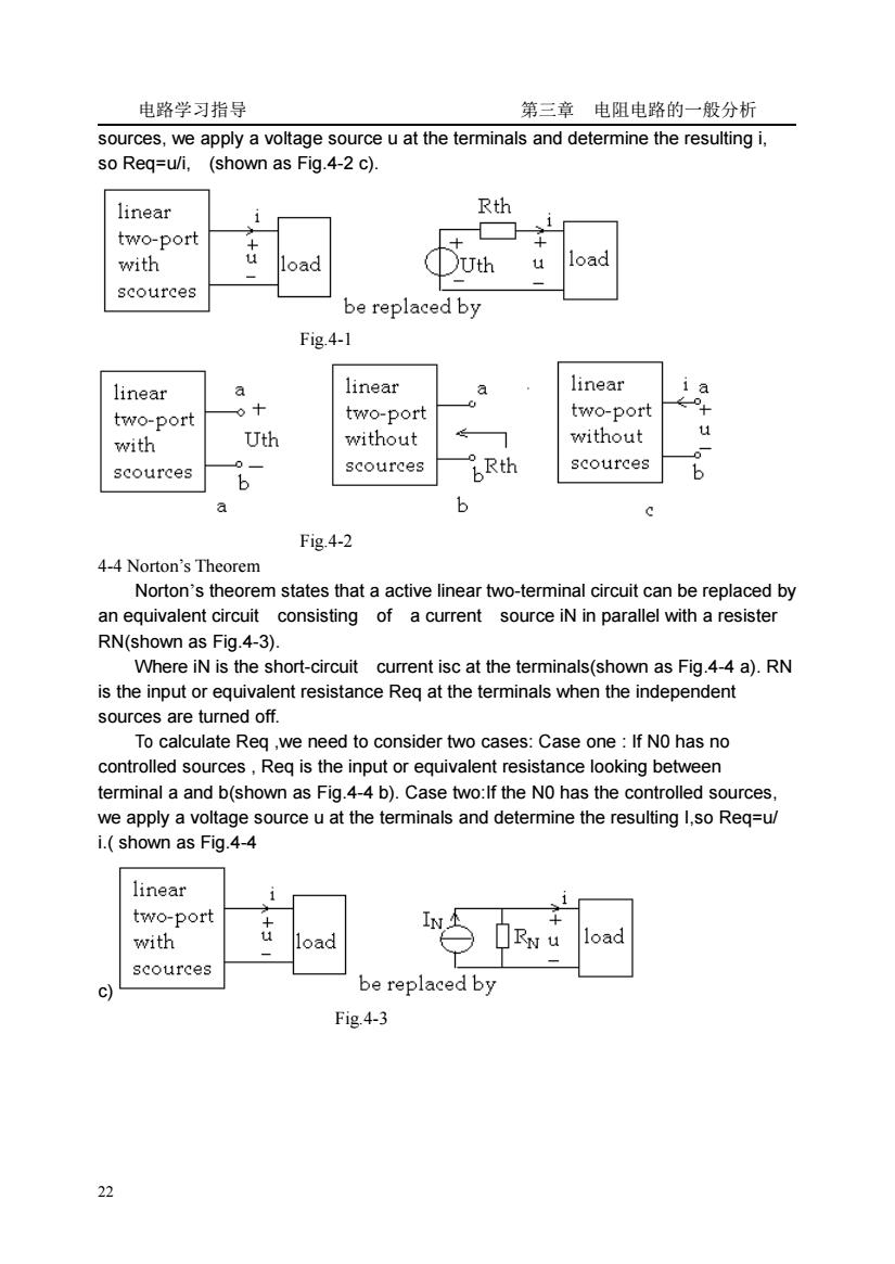
电路学习指导 第三章 电阻电路的一般分析 22 sources, we apply a voltage source u at the terminals and determine the resulting i, so Req=u/i, (shown as Fig.4-2 c). Fig.4-1 Fig.4-2 4-4 Norton’s Theorem Norton’s theorem states that a active linear two-terminal circuit can be replaced by an equivalent circuit consisting of a current source iN in parallel with a resister RN(shown as Fig.4-3). Where iN is the short-circuit current isc at the terminals(shown as Fig.4-4 a). RN is the input or equivalent resistance Req at the terminals when the independent sources are turned off. To calculate Req ,we need to consider two cases: Case one : If N0 has no controlled sources , Req is the input or equivalent resistance looking between terminal a and b(shown as Fig.4-4 b). Case two:If the N0 has the controlled sources, we apply a voltage source u at the terminals and determine the resulting I,so Req=u/ i.( shown as Fig.4-4 c) Fig.4-3
电路学习指导 第三章电阻电路的一般分析 linear linear linear two-port two-port two-por with without without scources scources RN scources b Fig.4-4 4-4 Maximum Power Transfer In many practical situations.a circuit is designed to provide power to a load.How does the load can draw the maximum power from the given source We assume that we can adjus the load resistance RL.If the entire circuit is replaced by its Thevenin equivalent except for the load.shown as Fig.4-5 Rth Uth R Fig.4-5 In many practical situations.a circuit is designed to provide power to a load.How does the load can draw the maximum power from the given source.We can prove that the maximum power is transferred to the load when the load resistance equals to the Thevenin resistance as seen from the load.That is when RL=Rth,the maximum power is: P= U 4Rth 4-6 Examples E4-1 Assume Io=1A and use linearity to find the actual value of the circuit in Fig E4-1 U222Q u 30 Is=15A 3 72 40 50 Fig.E4-1 Solution: If Io=1A,then Ul=(3+5)Io=8V and I1=U1/4=2A. Applying KCLat node lgives -1+3A S0U2=U1+2I2=8+6=14V,I3=U2/7=2A 23
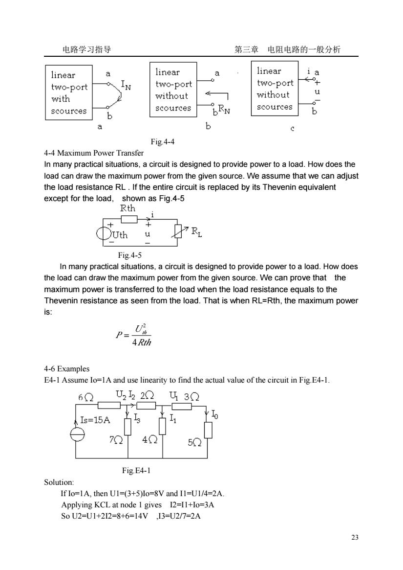
电路学习指导 第三章 电阻电路的一般分析 23 Fig.4-4 4-4 Maximum Power Transfer In many practical situations, a circuit is designed to provide power to a load. How does the load can draw the maximum power from the given source. We assume that we can adjust the load resistance RL . If the entire circuit is replaced by its Thevenin equivalent except for the load, shown as Fig.4-5 Fig.4-5 In many practical situations, a circuit is designed to provide power to a load. How does the load can draw the maximum power from the given source. We can prove that the maximum power is transferred to the load when the load resistance equals to the Thevenin resistance as seen from the load. That is when RL=Rth, the maximum power is: Rth U P th 4 2 = 4-6 Examples E4-1 Assume Io=1A and use linearity to find the actual value of the circuit in Fig.E4-1. Fig.E4-1 Solution: If Io=1A, then U1=(3+5)Io=8V and I1=U1/4=2A. Applying KCL at node 1 gives I2=I1+Io=3A So U2=U1+2I2=8+6=14V ,I3=U2/7=2A
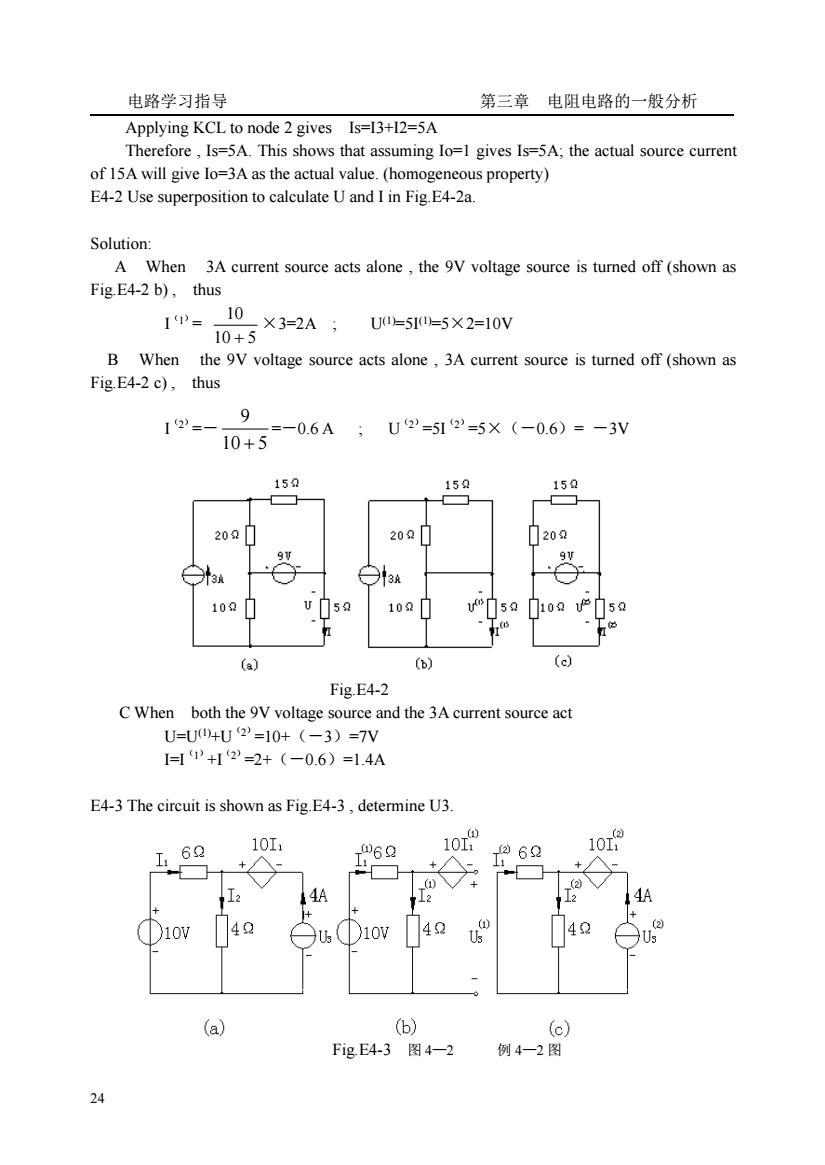
电路学习指导 第三章电阻电路的一般分析 Applying KCL to node 2 gives Is=13+12=5A Therefore,Is=5A.This shows that assuming Io=1 gives Is=5A;the actual source current of 15A will give Io=3A as the actual value.(homogeneous property) E4-2 Use superposition to calculate U and I in Fig.E4-2a. Solution A When 3A current source acts alone,the 9V voltage source is turned off (shown as Fig.E4-2 b),thus U0=5=5×2=10V B When the 9v voltage source acts alone 3A current source is turned off (shown as Fig.E4-2 c),thus 12= 9 =-0.6A;U2'=512=5×(-0.6)=-3V 10+5 15 159 15 20Q 200 20 9 9 100 10 (b) c Fig.E4-2 C When both the 9V voltage source and the 3A current source act U=U04U2'=10+(-3)=7V 1+2=2+ (-0.6)=14A E4-3 The circuit is shown as Fig.E4-3,determine U3. 10I 06Q 10 6 10u 4 3D10 4 4 (a) (b) FigE4-3图4-2 例4一2图 24
电路学习指导 第三章 电阻电路的一般分析 24 Applying KCL to node 2 gives Is=I3+I2=5A Therefore , Is=5A. This shows that assuming Io=1 gives Is=5A; the actual source current of 15A will give Io=3A as the actual value. (homogeneous property) E4-2 Use superposition to calculate U and I in Fig.E4-2a. Solution: A When 3A current source acts alone , the 9V voltage source is turned off (shown as Fig.E4-2 b) , thus I(1)= 10 5 10 + ×3=2A ; U(1)=5I (1)=5×2=10V B When the 9V voltage source acts alone , 3A current source is turned off (shown as Fig.E4-2 c) , thus I(2)=- 10 5 9 + =-0.6 A ; U(2)=5I(2)=5×(-0.6)= -3V Fig.E4-2 C When both the 9V voltage source and the 3A current source act U=U(1)+U(2)=10+(-3)=7V I=I(1)+I(2)=2+(-0.6)=1.4A E4-3 The circuit is shown as Fig.E4-3 , determine U3. Fig.E4-3 图 4—2 例 4—2 图

电路学习指导 第三章电阻电路的一般分析 A When the 10V voltage source acts alone,4A current source is replaced by open circuit (shown as Fig.E4-3 b),thus 1甲=P=9A U9=-1010+4I9=(-10+4)×1=-6V A When the 4A current source acts alone,10V voltage source is replaced by short circuit (shown as Fig.E4-3c),thus =- 4+6X4-1.6A 4 I2=4+I2)=4+(-1.6)=2.4A U2=-1012+412=-10×(-1.6)+4×2.4=25.6V S0U3=U9+U2=-6+25.6=19.6V E4-4 The circuit is shown as Fig.E4-4.No is a network without independent sources.When Us=4V,Is=2A,Ux=8V;when Us=7V,Is=1A,Ux=6V.When Us=2V,Ix=6A,Ux=? Solution: According superposition 0+U0 Ux=k Us+kols When Us=4V,Is=2A,Ux=8V. That is 8V=kiX4+k2X2=4kr+2k When Us=7V,Is=1A,Ux=6V, That is 6=7k+1k2 S0k1=0.4,k2=3.2Q Ux=0.4Us+3.22X1s Fig.E4-4 Thus,when Us=-2V,x=6A,Ux=0.4×2+3.2×6=20V E4-5 Determine the Thevenin equivalent circuit of the circuit shown as Fig.E4-5. 9V 1002 3 6V Uoc 62 162 102 102 b (a) (b) (c)
电路学习指导 第三章 电阻电路的一般分析 25 A When the 10V voltage source acts alone , 4A current source is replaced by open circuit (shown as Fig.E4-3 b) , thus I(1) 1 = I(2) 1 = 6 4 10 + =1A U(1) 3 =-10 I(1) 1 +4 I(1) 2 =(-10+4)×1=-6V A When the 4A current source acts alone , 10V voltage source is replaced by short circuit (shown as Fig.E4-3 c) , thus I(2) 1 =- 4 6 4 + =×4= -1.6A I(2) 1 = 4+ I(2) 1 = 4+(-1.6)=2.4A U(2) 3 = -10 I(2) 1 +4 I(2) 1 = -10×(-1.6)+4×2.4=25.6V So U 3 = U(1) 3 + U(2) 3 =-6+25.6=19.6V E4-4 The circuit is shown as Fig.E4-4, No is a network without independent sources . When Us=4V, Is=2A,,Ux=8V; when Us=7V,Is=1A,,Ux=6V. When Us=2V,Ix=6A,Ux=? Solution: According superposition Ux=k1Us+k2Is When Us=4V,Is=2A,Ux=8V, That is 8V=k1×4+k2×2=4k1+2k2 When Us=7V,Is=1A,Ux=6V, That is 6=7k1+1k2 So k1=0.4 , k 2=3.2Ω Ux=0.4Us+3.2Ω×Is Fig.E4-4 Thus , when Us=2V,Ix=6A, Ux= 0.4×2+3.2×6=20V E4-5 Determine the Thevenin equivalent circuit of the circuit shown as Fig.E4-5. (a) (b) (c) U U X