ELECTRIC CIRCUIT ELCTRIC CIRCUIT It is the purpose of electric circuit theory to furnish a means of describing the transfer of energy from a suitable source to appropriate engineering devices which are designed to achieve certain useful results.Through circuit theory ,for example ,we can readily analyze the generation,transmission,and application of electrical energy for home,commercial,and industrial uses
ELECTRIC CIRCUIT ELCTRIC ELCTRIC ELCTRIC ELCTRIC CIRCUIT CIRCUIT CIRCUIT CIRCUIT It is the purpose of electric circuit theory to furnish a means of describing the transfer of energy from a suitable source to appropriate engineering devices which are designed to achieve certain useful results. Through circuit theory ,for example ,we can readily analyze the generation, transmission, and application of electrical energy for home, commercial , and industrial uses
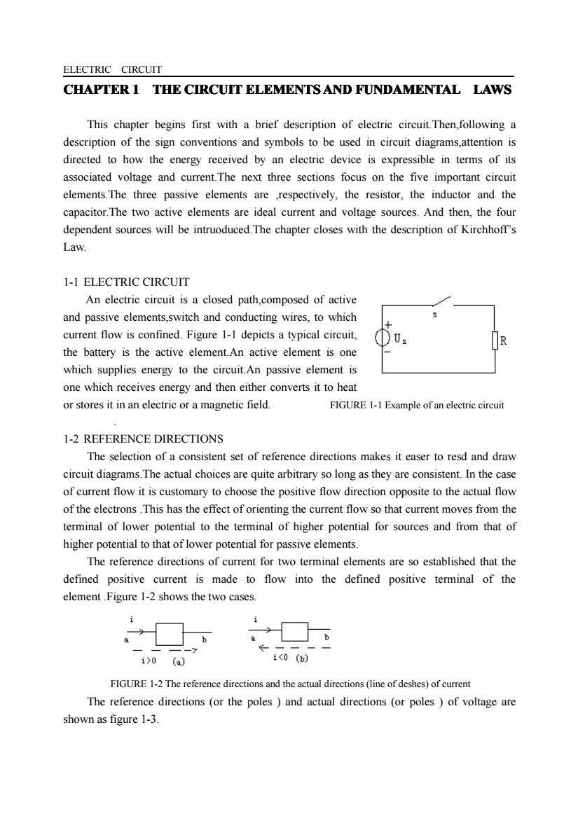
ELECTRIC CIRCUIT CHAPTER1 THE CIRCUIT ELEMENTS AND FUNDAMENTAL LAWS This chapter begins first with a brief description of electric circuit. Then, following a description of the sign conventions and symbols to be used in circuit diagrams,attention is directed to how the energy received by an electric device is expressible in terms of its associated voltage and current. The next three sections focus on the five important circuit elements. The three passive elements are ,respectively, the resistor, the inductor and the capacitor. The two active elements are ideal current and voltage sources. And then, the four dependent sources will be intruoduced. The chapter closes with the description of Kirchhoff's Law. 1-1 ELECTRIC CIRCUIT An electric circuit is a closed path,composed of active and passive elements,switch and conducting wires, to which + current flow is confined. Figure 1-1 depicts a typical circuit, Us R the battery is the active element. An active element is one which supplies energy to the circuit.An passive element is one which receives energy and then either converts it to heat or stores it in an electric or a magnetic field. FIGURE 1-1 Example of an electric circuit 1-2 REFERENCE DIRECTIONS The selection of a consistent set of reference directions makes it easer to resd and draw circuit diagrams. The actual choices are quite arbitrary so long as they are consistent. In the case of current flow it is customary to choose the positive flow direction opposite to the actual flow of the electrons. This has the effect of orienting the current flow so that current moves from the terminal of lower potential to the terminal of higher potential for sources and from that of higher potential to that of lower potential for passive elements. The reference directions of current for two terminal elements are so established that the defined positive current is made to flow into the defined positive terminal of the element. Figure 1-2 shows the two cases. i i → a b a b i>0 (a) i<0(b) FIGURE 1-2 The reference directions and the actual directions (line of deshes) of current The reference directions (or the poles)and actual directions (or poles)of voltage are shown as figure 1-3
ELECTRIC CIRCUIT CHAPTER CHAPTER CHAPTER CHAPTER 1 THE CIRCUIT CIRCUIT CIRCUIT CIRCUIT ELEMENTS ELEMENTS ELEMENTS ELEMENTS AND FUNDAMENTAL FUNDAMENTAL FUNDAMENTAL FUNDAMENTAL LAWS This chapter begins first with a brief description of electric circuit.Then,following a description of the sign conventions and symbols to be used in circuit diagrams,attention is directed to how the energy received by an electric device is expressible in terms of its associated voltage and current.The next three sections focus on the five important circuit elements.The three passive elements are ,respectively, the resistor, the inductor and the capacitor.The two active elements are ideal current and voltage sources. And then, the four dependent sources will be intruoduced.The chapter closes with the description of Kirchhoff’s Law. 1-1 ELECTRIC CIRCUIT An electric circuit is a closed path,composed of active and passive elements,switch and conducting wires, to which current flow is confined. Figure 1-1 depicts a typical circuit, the battery is the active element.An active element is one which supplies energy to the circuit.An passive element is one which receives energy and then either converts it to heat or stores it in an electric or a magnetic field. FIGURE 1-1 Example of an electric circuit . 1-2 REFERENCE DIRECTIONS The selection of a consistent set of reference directions makes it easer to resd and draw circuit diagrams.The actual choices are quite arbitrary so long as they are consistent. In the case of current flow it is customary to choose the positive flow direction opposite to the actual flow of the electrons .This has the effect of orienting the current flow so that current moves from the terminal of lower potential to the terminal of higher potential for sources and from that of higher potential to that of lower potential for passive elements. The reference directions of current for two terminal elements are so established that the defined positive current is made to flow into the defined positive terminal of the element .Figure 1-2 shows the two cases. FIGURE 1-2 The reference directions and the actual directions (line of deshes) of current The reference directions (or the poles ) and actual directions (or poles ) of voltage are shown as figure 1-3
ELECTRIC CIRCUIT u>o (a) u<0) FIGURE 1-3The reference direction and actual direction(line of deshes)of voltage 13 EneRGYAND POWER Figure 1-4 depicts a battery delivering energy to a circuit element appearing between terminals c and d.It is assumed that the current flowing through the device is i and the potential difference(voltage)etween the terminals is u The energy that the battery delivered or the passive element absorbed is 6 f=() (1-1) Which shows that the energy absorbed is given by the product of the voltage,the current,and the time. . Power is the time rate of doing work.By letting p denote power,it can be expressed mathematically as FIGURE 1-4 Example circuit of delivering energy P=w/t (w) (1-2) Upon substituting Eq.(1-1),an alternative expression results P-ui (w) (1-3) Note that power expresses a device's energy-delivering or energy-absorbing capabilities per uint of time The reference direction for power must be consistent with the reference directions for voltage and current,because power is dependent upon the product of these two quantities.If the actual current and voltage have the same signs as the assumed directions,then the power is positive.This means that the passive element receives energy from the source.When the actual current and voltage are both opposite to the assumed positive directions,the conclusion remains the same because a product of two negative quantities is involved.The detail is shown as FIGURE 1-5. 0 器8 () FIGURE 1-5 The power 1-4 THE RISISTANCE PARAMETER Resistance is one of three basic parameters of electric circuit theory.Strictly
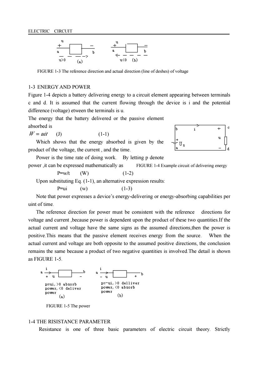
ELECTRIC CIRCUIT FIGURE 1-3 The reference direction and actual direction (line of deshes) of voltage 1-3 ENERGY AND POWER Figure 1-4 depicts a battery delivering energy to a circuit element appearing between terminals c and d. It is assumed that the current flowing through the device is i and the potential difference (voltage) etween the terminals is u. The energy that the battery delivered or the passive element absorbed is W = uit (J) (1-1) Which shows that the energy absorbed is given by the product of the voltage, the current , and the time. Power is the time rate of doing work. By letting p denote power ,it can be expressed mathematically as FIGURE 1-4 Example circuit of delivering energy P=w/t (W) (1-2) Upon substituting Eq. (1-1), an alternative expression results: P=ui (w) (1-3) Note that power expresses a device’s energy-delivering or energy-absorbing capabilities per uint of time. The reference direction for power must be consistent with the reference directions for voltage and current ,because power is dependent upon the product of these two quantities.If the actual current and voltage have the same signs as the assumed directions,then the power is positive.This means that the passive element receives energy from the source. When the actual current and voltage are both opposite to the assumed positive directions, the conclusion remains the same because a product of two negative quantities is involved.The detail is shown as FIGURE 1-5. FIGURE 1-5 The power 1-4 THE RISISTANCE PARAMETER Resistance is one of three basic parameters of electric circuit theory. Strictly
ELECTRIC CIRCUIT speaking ,every circuit element exhibits some degree of resistance-but often,as in the case of inductor,capacitors,or ordinary wire connections between various circuit elements,it is of minor importance. Resistor is a two terminal element,its symbol is as figure 1-6.Since by Ohm's law we have U=Ri (1-4) The reference direction of voltage and current in equation(1-4)are same and if the reference direction of voltage and current are inversed,we should insert a""in front of Ri. R is proportional to the voltage and inverse proportional to the current.R is an element and is independent of the current and voltage. =-1 (a) FIGURE 1-6 Symbol of resistance The u-i characteristic of resistance is depicted in Fig 1-7. u() slope:R ohms /0 (A) FIGURE 1-7u-I characteristic of resistance. The resistance parameter may also be looked upon in terms of its characteristic property of converting electrical energy into heat energy.If Eqs.(1-3)and(1-4)are combined,it follows that the power absorbed by a resistor is P=Ri (1-5) The energy is m=R21 (1-6) All current-carrying conductors and resistors involve a heat loss which occurs at a rate given by.At first this heat is stored in the body of the material,thereby bringing about a temperature rise.As soon as the body temperature exceeds the ambient temperature ,however ,heat is transferred to the surrounding medium.If the power-dissipating capability of a resister or rheostat is inadequate for a specified rating it can easily bur out.To
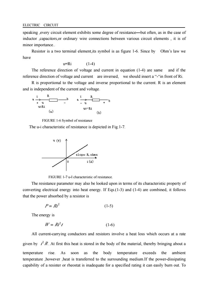
ELECTRIC CIRCUIT speaking ,every circuit element exhibits some degree of resistance—but often, as in the case of inductor ,capacitors,or ordinary wire connections between various circuit elements , it is of minor importance. Resistor is a two terminal element,its symbol is as figure 1-6. Since by Ohm’s law we have u=Ri (1-4) The reference direction of voltage and current in equation (1-4) are same and if the reference direction of voltage and current are inversed, we should insert a “-“in front of Ri. R is proportional to the voltage and inverse proportional to the current. R is an element and is independent of the current and voltage. FIGURE 1-6 Symbol of resistance The u-i characteristic of resistance is depicted in Fig.1-7. FIGURE 1-7 u-I characteristic of resistance. The resistance parameter may also be looked upon in terms of its characteristic property of converting electrical energy into heat energy. If Eqs.(1-3) and (1-4) are combined, it follows that the power absorbed by a resistor is 2 P = Ri (1-5) The energy is W Ri t 2 = (1-6) All current-carrying conductors and resistors involve a heat loss which occurs at a rate given by i R2 . At first this heat is stored in the body of the material, thereby bringing about a temperature rise. As soon as the body temperature exceeds the ambient temperature ,however ,heat is transferred to the surrounding medium.If the power-dissipating capability of a resister or rheostat is inadequate for a specified rating it can easily burn out. To
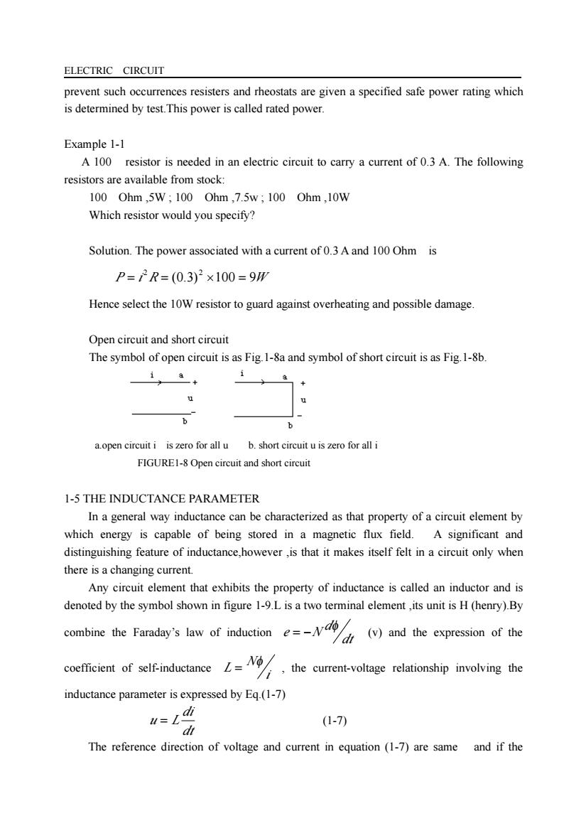
ELECTRIC CIRCUIT prevent such occurrences resisters and rheostats are given a specified safe power rating which is determined by test.This power is called rated power Example 1-1 A 100 resistor is needed in an electric circuit to carry a current of 0.3 A.The following resistors are available from stock: 100Ohm,5w,100Ohm,7.5w;100Ohm,10W Which resistor would you specify? Solution.The power associated with a current of 0.3A and 100 Ohm is P=2R=(0.3)2×100=9m Hence select the 10W resistor to guard against overheating and possible damage. Open circuit and short circuit The symbol of open circuit is as Fig.1-8a and symbol of short circuit is as Fig 1-8b + 31+ a.open circuit i iszero for all u b.short eircuituiszero foralli FIGURE1-8Open circuit and short circuit 1-5 THE INDUCTANCE PARAMETER In a general way inductance can be characterized as that property of a circuit element by which energy is capable of being stored in a magnetic flux field.A significant and distinguishing feature of inductance,however,is that it makes itself felt in a circuit only when there is a changing current. Any circuit element that exhibits the property of inductance is called an inductor and is denoted by the symbol shown in figure 1-9.L is a two terminal element,its unit is H(henry).By combine the Faraday's aw of induction()and the of te coefficient of self-inductance the current-voltage relationship involving the inductance parameter is expressed by Eq.(1-7) (1-7) The reference direction of voltage and current in equation(1-7)are same and if the
ELECTRIC CIRCUIT prevent such occurrences resisters and rheostats are given a specified safe power rating which is determined by test.This power is called rated power. Example 1-1 A 100 resistor is needed in an electric circuit to carry a current of 0.3 A. The following resistors are available from stock: 100 Ohm ,5W ; 100 Ohm ,7.5w ; 100 Ohm ,10W Which resistor would you specify? Solution. The power associated with a current of 0.3 A and 100 Ohm is P i R (0.3) 100 9W 2 2 = = × = Hence select the 10W resistor to guard against overheating and possible damage. Open circuit and short circuit The symbol of open circuit is as Fig.1-8a and symbol of short circuit is as Fig.1-8b. a.open circuit i is zero for all u b. short circuit u is zero for all i FIGURE1-8 Open circuit and short circuit 1-5 THE INDUCTANCE PARAMETER In a general way inductance can be characterized as that property of a circuit element by which energy is capable of being stored in a magnetic flux field. A significant and distinguishing feature of inductance,however ,is that it makes itself felt in a circuit only when there is a changing current. Any circuit element that exhibits the property of inductance is called an inductor and is denoted by the symbol shown in figure 1-9.L is a two terminal element ,its unit is H (henry).By combine the Faraday’s law of induction dt d e N φ = − (v) and the expression of the coefficient of self-inductance i N L φ = , the current-voltage relationship involving the inductance parameter is expressed by Eq.(1-7) dt di u = L (1-7) The reference direction of voltage and current in equation (1-7) are same and if the