电路学习指导 第三章电阻电路的一般分析 CAPTER 8 THREE PHASE CIRCUIT 8-1 Three Phase Voltage same am=U2 coso enerator co Uen urces having the se with eac 120 Uan ree.Balanced three phase vo =U√2 cos(ot-120°)Fig Fig.8-1): -120 u=U√2cos(1+120°) Ubn Fig.8-1 8-2 Three Phase System A typical three 0 1 to loads by three or four wires. The v Uan a Cba + Uab a connected(shown as Fig.8-2 a and b re Ubn + - b + b n O+ t Ucn Ube C 0 Fig.8-2 a Fig.8-2.b Voltage: are between lines a,b,and c and the neutral line n respectively, and are called phase voltages. =UP∠0°,Um=Up∠-120°,U=U,∠120° They are known as abc or positive sequence. The phasor diagram is shown as Fig.8-1 (acb called negative seq.) The three load can also be connected as wye (three wire or four wire)or delta. Shown as Fig.8-3 a and b repectively.: a Z1 oa Can Zs a Z1 A Q Z1 Z1 Ucn ZN N b Z2 Z3 n O+ Zsb 女 Z B Z2 C b Z2 UbnZs Z C Z3 To ba Z3 n C Z1=Z2=23,ZA=3Z, There are four possible connections: Y-Y,Y-delta, delta-delta,delta-Y. the balanced Y-Y connection is shown as Fig.8-4, and Balanced Wye-wye Connection Because And Z=2,+Z1+Z 21 Ub=U-U=3U∠30°,UA=3Um∠30°,U=3U∠30° 34m=0
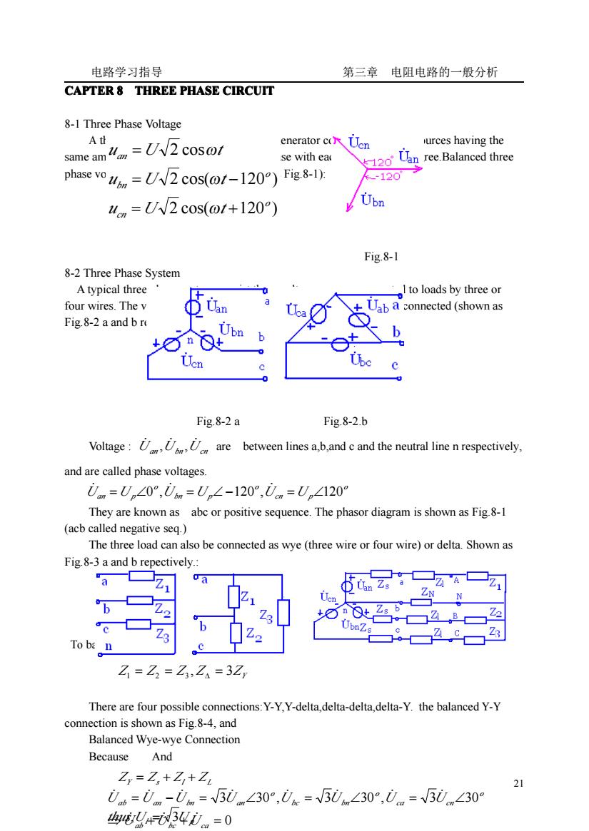
电路学习指导 第三章 电阻电路的一般分析 21 CAPTER 8 THREE PHASE CIRCUIT CIRCUIT CIRCUIT CIRCUIT 8-1 Three Phase Voltage A three phase system is produced by a generator consisting of three sources having the same amplitude and frequency but out of phase with each other by 120 degree.Balanced three phase voltages are (phasor diagram shown as Fig.8-1): Fig.8-1 8-2 Three Phase System A typical three phase system consist three voltage sources connected to loads by three or four wires. The voltages sources can be either wye-connected or delta-connected (shown as Fig.8-2 a and b repectively). Fig.8-2 a Fig.8-2.b Voltage : U an U bn U cn ̇ ̇ ̇ , , are between lines a,b,and c and the neutral line n respectively, and are called phase voltages. They are known as abc or positive sequence. The phasor diagram is shown as Fig.8-1 (acb called negative seq.) The three load can also be connected as wye (three wire or four wire) or delta. Shown as Fig.8-3 a and b repectively.: Fig.8-3 a Fig.8-3.b Fig.8-4 To balanced load There are four possible connections:Y-Y,Y-delta,delta-delta,delta-Y. the balanced Y-Y connection is shown as Fig.8-4, and Balanced Wye-wye Connection Because And 2 cos( 120 ) 2 cos( 120 ) 2 cos o cn o bn an u U t u U t u U t = + = − = ω ω ω o cn p o bn p o Uan =U p∠0 ,U =U ∠ −120 ,U =U ∠120 ̇ ̇ ̇ Z Z Z Z 3ZY , 1 = 2 = 3 ∆ = ZY = Zs + Zl + ZL 0 3 30 , 3 30 , 3 30 ⇒ + + = = − = ∠ = ∠ = ∠ ab bc ca o ca cn o bc bn o ab an bn an U U U U U U U U U U U ̇ ̇ ̇ ̇ ̇ ̇ ̇ ̇ ̇ ̇ ̇ Ul U p thus, = 3
电路学习指导 第三章电阻电路的一般分析 0n=0+0+0)1Z 31Z+1/Zx hs,1-么。-么=2 Z Z :1-么=1∠-120 Z 巴=1,∠120° Z →i。+i。+i.=0=in Thus,the neutral line can thus be removed without affecting the system The three phase voltages and the three line voltages of the load are 0w=Z1, {0av=Zis=0wL-120°→0w+Uay+Uy=0 0cw=Z,1.=0w∠120 Un=Uw amd,Uw=Z,1。=0w∠-120°→0w+Uaw+Ucw=0 0cw=Z,i.=0w∠120° While the line current is the current in each line,the phase current is the current in each phase of the source or load.in the Y-Y system,//=/pAn alternative way of analyzing a ba-lanced Y-Y system is to do so a"per phase"basis.Say,phase a(shown as Fig 8-5). Fig.8-5 Fig.8-6 Thus From la,we use the phase sequence to obtain other line currents.Thus,as long as the system is balanced,we need only analyze one phase.We may do this even if the neutral line is absent,as in the three-wire system
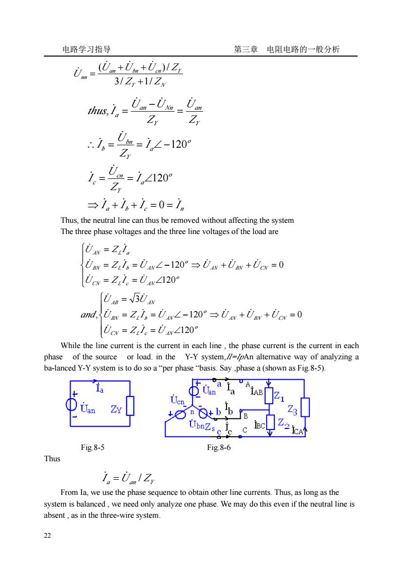
电路学习指导 第三章 电阻电路的一般分析 22 Thus, the neutral line can thus be removed without affecting the system The three phase voltages and the three line voltages of the load are While the line current is the current in each line , the phase current is the current in each phase of the source or load. in the Y-Y system,Il=IpAn alternative way of analyzing a ba-lanced Y-Y system is to do so a “per phase “basis. Say ,phase a (shown as Fig.8-5). Fig.8-5 Fig.8-6 Thus From Ia, we use the phase sequence to obtain other line currents. Thus, as long as the system is balanced , we need only analyze one phase. We may do this even if the neutral line is absent , as in the three-wire system. Y N an bn cn Y nn Z Z U U U Z U 3/ 1/ ( )/ + + + = ̇ ̇ ̇ ̇ a b c n o a Y cn c o a Y bn b Y an Y an Nn a I I I I I Z U I I Z U I Z U Z U U thus I ̇ ̇ ̇ ̇ ̇ ̇ ̇ ̇ ̇ ̇ ̇ ̇ ̇ ̇ ⇒ + + = = = = ∠ ∴ = = ∠ − = − = 0 120 120 , 0 120 120 3 , 0 120 120 ⇒ + + = ⎪ ⎪ ⎩ ⎪⎪ ⎨ ⎧ = = ∠ = = ∠ − = ⇒ + + = ⎪ ⎩ ⎪ ⎨ ⎧ = = ∠ = = ∠ − = AN BN CN o CN L c AN o BN L b AN AB AN AN BN CN o CN L c AN o BN L b AN AN L a U U U U Z I U U Z I U U U and U U U U Z I U U Z I U U Z I ̇ ̇ ̇ ̇ ̇ ̇ ̇ ̇ ̇ ̇ ̇ ̇ ̇ ̇ ̇ ̇ ̇ ̇ ̇ ̇ ̇ ̇ a U an ZY I / ̇ = ̇
电路学习指导 第三章电阻电路的一般分析 Balanced Wye-delta Connection A balanced Y-delta system con-sists of a balanced Y-connected source feeding a balanced delta-connected load(shown as Fig.8-6) assume,U=Un∠0% 0=06=V3U∠30 0=Uac=V30∠-90 Line volfige arequal the e across the load impedances for this system configuration.Thus ,the phase currents are 7-,- Uc Z、 These currents have the same magnitude but are out of phase with each other by 120 degree in=1B-1c=1Bv3∠-30° i=1cV3∠-30°-j∠-1209 1.=cV3∠-30°=1,∠120 Showing that the magnitude Il of the line current is the square root of 3 times the magnitude Ip of the phase current.Or I=V31 An alterative way of analyzing the Y-delta circuit is to transform the delta-connected load to an equiva-lent Y-connected load.then,have a Y-Y connected circuit. 8-3 Power in a Balanced SystemInstantaneous power is: P=Pa+Ps+pe=ului+ugcis+ucde P3Hln9s6小BsZ,cos∠0 if,uav =2U cosot,i,=2/cos(01-0) Thus the total instantaneous power in a balanced three phase system is constant.This result is true whether the load is Y or delta connectedThe average power of three phase load is For a Y-connected load, I=I,bm,U=√3U For a delta-connected load, 1=131.but,U,=Up Similarly 0=30.3=35=307。 =P+0=5Ul0 23
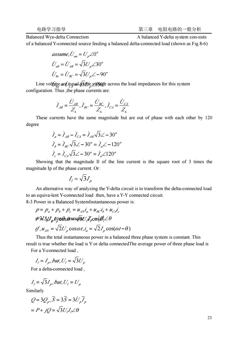
电路学习指导 第三章 电阻电路的一般分析 23 Balanced Wye-delta Connection A balanced Y-delta system con-sists of a balanced Y-connected source feeding a balanced delta-connected load (shown as Fig.8-6) Line voltage are equal to the voltage across the load impedances for this system configuration. Thus ,the phase currents are: These currents have the same magnitude but are out of phase with each other by 120 degree Showing that the magnitude Il of the line current is the square root of 3 times the magnitude Ip of the phase current. Or: An alternative way of analyzing the Y-delta circuit is to transform the delta-connected load to an equiva-lent Y-connected load .then, have a Y-Y connected circuit. 8-3 Power in a Balanced SystemInstantaneous power is: Thus the total instantaneous power in a balanced three phase system is constant. This result is true whether the load is Y or delta connectedThe average power of three phase load is For a Y-connected load , For a delta-connected load , Similarly o ca CA p o bc BC p o ab AB p o an p U U U U U U U U U assume U U 3 150 3 90 3 30 , 0 = = ∠ = = ∠− = = ∠ = ∠ ̇ ̇ ̇ ̇ ̇ ̇ ̇ ∆ ∆ ∆ = = = Z U I Z U I Z U I CA CA BC BC AB AB ̇ ̇ ̇ ̇ ̇ ̇ , , o a o c CA o a o b BC o a AB CA AB I I I I I I I I I I 3 30 120 3 30 120 3 30 = ∠− = ∠ = ∠− = ∠ − = − = ∠− ̇ ̇ ̇ ̇ ̇ ̇ ̇ ̇ ̇ ̇ l p I = 3I , 2 cos , 2 cos( ) 3 cos , : ω ω θ θ θ = = − = = ∠ = + + = + + if u U t i I t U I assume Z Z p p p p u i u i u i AN p a p p p Y a b c AN a BC b CA c P = 3U pI p cosθ = 3UlI l cosθ l p but Ul U p I = I , , = 3 l p but Ul U p I = 3I , , = = + = ∠θ = = = l l p p p P jQ U I Q Q S S U I 3 ~ 3 ~ 3 ~ 3 , ̇

电路学习指导 第三章电阻电路的一般分析 The power measurement P=PI+P2 (shown as Fig8-7)When it is a balanced circuit (shown as Fig-8s is opened) 6==立6830) load losed) anced volt:N mea Co 6 Because: 0w=0+0+0L UAN S ++ N The phase diagram is shown as Fig 8-9 When there is not a neutral line the three phase we can use a neutral line to force each phase independent E8-1 A balanced Y-Y connected three phas 心uw.g.E8-la,where UA=220245V,determine Ua.Uc.UAB.Uc.Uca,and draw the phasor diagram. Solution U=220∠45V UAB=380∠75V: U=220∠-75V,Uc=380∠-45V: Uc=220∠165V, UcA=380∠195V。 the phasor diagram is shown as Fig.E8-1 b. 。C o N Fig.E8-1 a Fig.E8-1 b E8-2 A balanced Y-Y connected three phase circuit shown as Fig.E8-2a, where0=220∠0V,Z=(6+j8)2,Z=0.06+j0.06)2,Z=(0.01+j0.02)2 determine //B,/c,the phase voltage and line voltage of the load Solution The circuit can be simplified as one phase to calculate shown as Fig.E8-2b 24
电路学习指导 第三章 电阻电路的一般分析 24 The power measurement P=P1+P2 (shown as Fig.8-7)When it is a balanced circuit (shown as Fig.8-8 s is opened) Unbalanced circuit (shown as Fig.8-8 s is closed) An unbalanced system is due to unbalanced voltage source or an unbalanced load. We mean the load Because: The phase diagram is shown as Fig.8-9 When there is not a neutral line ,the three phase will interact each other, So we can use a neutral line to force each phase independent E8-1 A balanced Y-Y connected three phase circuit shown as Fig.E8-1a, where U̇ A = 220∠45°V ,determine UB ̇ ,UC ̇ , UAB ̇ ,UBC ̇ ,UCA ̇ ,and draw the phasor diagram. Solution : U̇ A = 220∠45°V , U̇ AB = 380∠75°V ; U̇B = 220∠ − 75°V , U̇BC = 380∠ − 45°V ; U̇C = 220∠165°V , U̇CA = 380∠195°V 。 the phasor diagram is shown as Fig.E8-1 b. Fig.E8-1 a Fig.E8-1 b E8-2 A balanced Y-Y connected three phase circuit shown as Fig.E8-2a, where U̇ A = 220∠0°V , Z = (6 + j8)Ω , Z L = (0.06 + j0.06)Ω , Z N = (0.01+ j0.02)Ω , determine I A ̇ , I B ̇ , I C ̇ , the phase voltage and line voltage of the load. Solution The circuit can be simplified as one phase to calculate shown as Fig.E8-2b ⎪ ⎩ ⎪ ⎨ ⎧ = = + = = − ] cos( 30 ) ~ Re[ ] cos( 30 ) ~ Re[ 2 1 o BC B BC B o AC A AC A P U I U I P U I U I ϕ ϕ ̇ ̇ A B C A A B B C C NN Y Y Y U Y U Y U Y U + + + + = ̇ ̇ ̇ ̇
电路学习指导 第三章电阻电路的一般分析 A色gk名 N A凸4玉名 1N' g4g名 Fig.E8-2 a Fig.E8-2 b 220∠0° 么+Z006+05+6+8=2182∠-5306A 7B=21.82∠-173.06°A,c=21.82∠66.94°A phase voltage:Uaw=ZIa=21.82∠-53.06°×(6+j8)=218.2∠0.07V 0=218.2∠-119.93V,0w=218.2∠120.07V 1 ine voltage:0=V3∠30Uaw=377.8∠30.07V Uc=377.8∠-89.93V,c=377.8∠150.07V E8-3 A balanced Y-delta connected three phase circuit shown as Fig.E8-3a,where the line impedance is Z=(3+j4),the load is Z=(19.2+jl4.4)Q,determine line current A,/a Ic,and phase current Aw,/c,/cA Solution Tur the delta cometed loadtYcometed od Let Ua as the reference voltage,that is i=22020 The single phase circuit is shown as Fig.E8-3b UA 220∠0° 么Z+Z8+j4w+64+j4周171∠-431A 令上凸A B凸g 2 N TB'c ,z0 z sis Fig.E8-3 a Fig.E8-3 b B=17.1∠-163.1°A,e=17.1∠76.9°A because7A=√5iag∠-30° 25
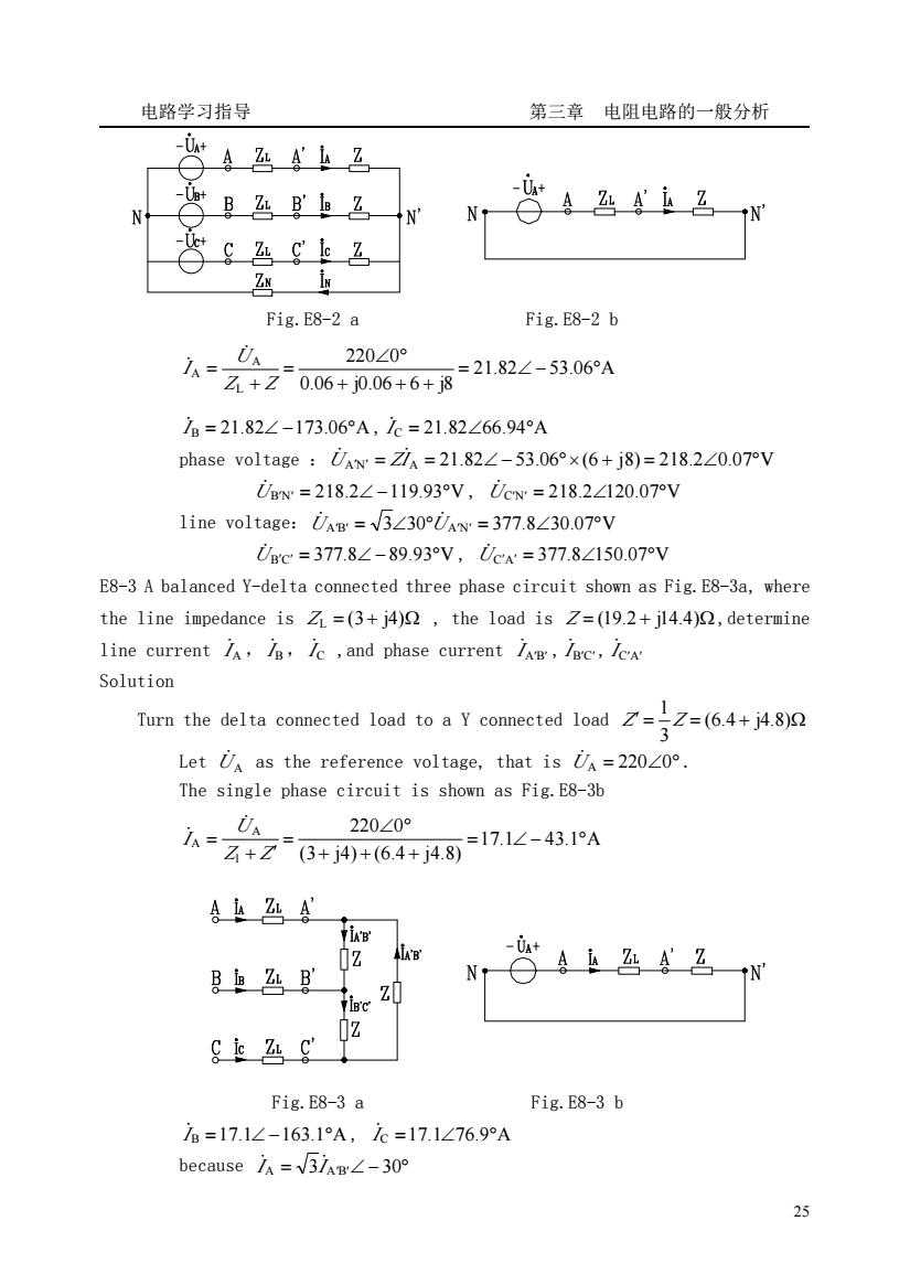
电路学习指导 第三章 电阻电路的一般分析 25 Fig.E8-2 a Fig.E8-2 b 21.82 53.06 A 0.06 j0.06 6 j8 220 0 L A A = ∠ − ° + + + ∠ ° = + = Z Z U I ̇ ̇ I ̇B = 21.82∠ −173.06°A , I ̇C = 21.82∠66.94°A phase voltage :U̇ A′N′ = ZI ̇A = 21.82∠ − 53.06°×(6 + j8) = 218.2∠0.07°V U̇ B′N′ = 218.2∠ −119.93°V , U̇C′N′ = 218.2∠120.07°V line voltage:U̇ A′B′ = 3∠30°U̇ A′N′ = 377.8∠30.07°V U̇ B′C′ = 377.8∠ − 89.93°V , U̇C′A′ = 377.8∠150.07°V E8-3 A balanced Y-delta connected three phase circuit shown as Fig.E8-3a, where the line impedance is Z L = (3 + j4)Ω , the load is Z = (19.2 + j14.4)Ω,determine line current I A ̇ , I B ̇ , I C ̇ ,and phase current I A′B′ ̇ , I B′C′ ̇ , I C′A′ ̇ Solution Turn the delta connected load to a Y connected load ′ = = (6.4 + j4.8)Ω 3 1 Z Z Let UA ̇ as the reference voltage, that is UA = 220∠0° ̇ . The single phase circuit is shown as Fig.E8-3b 17.1 43.1 A (3 j4) (6.4 j4.8) 220 0 l A A = ∠ − ° + + + ∠ ° = + ′ = Z Z U I ̇ ̇ Fig.E8-3 a Fig.E8-3 b I ̇B =17.1∠ −163.1°A , I ̇C =17.1∠76.9°A because I A = 3I A′B′∠ − 30° ̇ ̇