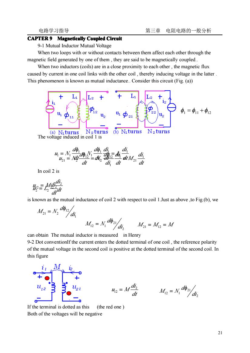
电路学习指导 第三章电阻电路的一般分析 CAPTER 9 Magnetically Coupled Circuit 9-1 Mutual Inductor Mutual Voltage When two loops with or without contacts between them affect each other through the magnetic field generated by one of them, they are said to be magnetically coupled. When two inductors(coils)are in a close proximity to each other, the magnetic flux caused by current in one coil links with the other coil, thereby inducing voltage in the latter. This phenomenon is known as mutual inductance. Consider this circuit (Fig. (a) + L1 L2 + + L1 L2 11 12 U1 12 U1 22 1=11+中12 11 12 21 A U2 (a) N1turns N2turns (b) Niturns N2turns The voltage induced in coil 1 is do dì In coil 2 is is known as the mutual inductance of coil 2 with respect to coil 1.Just as above,to Fig.(b), we M21=N22/d d21 M12=N12ydi,M21=M12=M can obtain The mutual inductor is measured in Henry 9-2 Dot conventionIf the current enters the dotted terminal of one coil, the reference polarity of the mutual voltage in the second coil is positive at the dotted terminal of the second coil. In this figure i1 M 12 A 0 0 + ○ + ○ 11 12 1 21 2=M MI-N a an 0 If the terminal is dotted as this(the red one) Both of the voltages will be negative 21
电路学习指导 第三章 电阻电路的一般分析 21 CAPTER 9 Magnetically Magnetically Magnetically Magnetically Coupled Coupled Coupled Coupled Circuit Circuit Circuit Circuit 9-1 Mutual Inductor Mutual Voltage When two loops with or without contacts between them affect each other through the magnetic field generated by one of them , they are said to be magnetically coupled. When two inductors (coils) are in a close proximity to each other , the magnetic flux caused by current in one coil links with the other coil , thereby inducing voltage in the latter . This phenomenon is known as mutual inductance. Consider this circuit (Fig. (a)) The voltage induced in coil 1 is In coil 2 is is known as the mutual inductance of coil 2 with respect to coil 1.Just as above ,to Fig.(b), we can obtain The mutual inductor is measured in Henry 9-2 Dot conventionIf the current enters the dotted terminal of one coil , the reference polarity of the mutual voltage in the second coil is positive at the dotted terminal of the second coil. In this figure If the terminal is dotted as this (the red one ) Both of the voltages will be negative φ1 = φ11 +φ12 dt di L dt di di d N dt d u N 1 1 1 1 1 1 1 1 = 1 = = φ φ dt di M dt di di d N dt d u N 1 21 1 1 12 2 12 21 = 2 = = φ φ 1 12 21 2 di d M N φ = dt di u L 2 2 = 2 dt di u M 2 12 = 12 2 21 12 1 di d M N φ = M 21 = M12 = M dt di u M 2 12 = 2 21 12 1 di d M N φ =
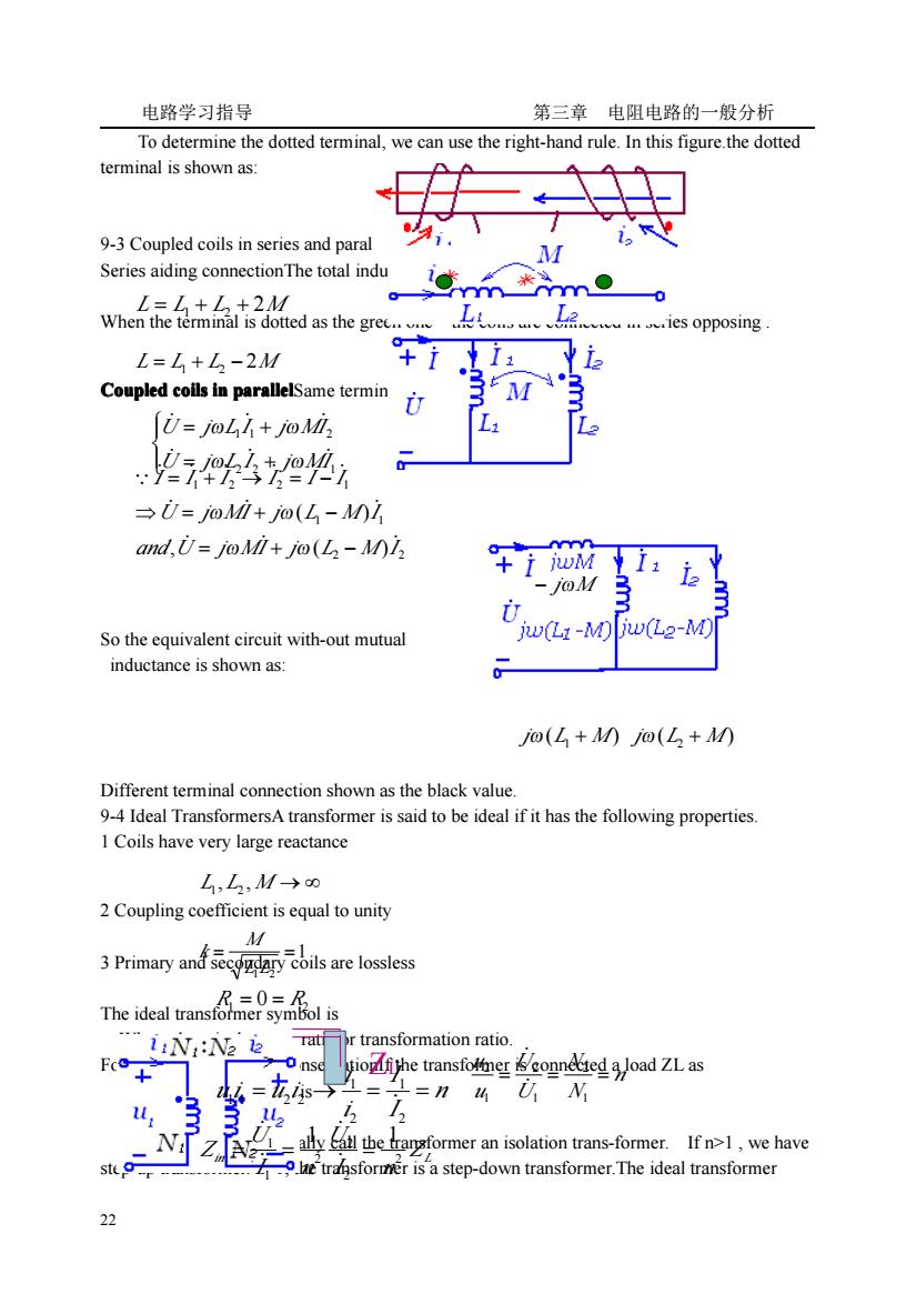
电路学习指导 第三章电阻电路的一般分析 To determine the dotted terminal,we can use the right-hand rule.In this figure.the dotted terminal is shown as: 9-3 Coupled coils in series and paral Series aiding connectionThe total indu wh品钻点2 dthe in*m .ies opposing L=L+L-2M (ia Coupled coils in parallelSame termin M U=jolh+joMl 243恤 →0=oi+jo(L-01 and,U=joMi+jo(L-M)1 -10MB So the equivalent circuit with-out mutual jw(L1-M)jw(L2-M) inductance is shown as: o(L+0@(L+0 Different terminal connection shown as the black value. 9-4 Ideal TransformersA transformer is said to be ideal if it has the following properties. 1 Coils have very large reactance L,L,M→o 2 Coupling coefficient is equal to unity 3Primary are lossles The idealaso iiN:N2 ie rtransformation ratio F tiofithe transfotmer connted a load ZLas u. the arformer an isolation trans-former.Ifn1,we have 9hetransforner is a step-down transformer.The ideal transformer
电路学习指导 第三章 电阻电路的一般分析 22 To determine the dotted terminal, we can use the right-hand rule. In this figure.the dotted terminal is shown as: 9-3 Coupled coils in series and parallelCoupled Coupled Coupled Coupled coils in series Series aiding connectionThe total inductance is When the terminal is dotted as the green one the coils are connected in series opposing . Coupled Coupled Coupled Coupled coils in parallel parallel parallel parallelSame terminal connection So the equivalent circuit with-out mutual inductance is shown as: Different terminal connection shown as the black value. 9-4 Ideal TransformersA transformer is said to be ideal if it has the following properties. 1 Coils have very large reactance 2 Coupling coefficient is equal to unity 3 Primary and secondary coils are lossless The ideal transformer symbol is Where the n is the turns ratio or transformation ratio. For the reason of power conservationIf the transformer is connected a load ZL as The input impedance is When n=1 , we generally call the transformer an isolation trans-former. If n>1 , we have step-up transformer. n<1, the transformer is a step-down transformer.The ideal transformer L = L1 + L2 + 2M L = L1 + L2 − 2M ⎪ ⎩ ⎪ ⎨ ⎧ = + = + 2 2 1 1 1 2 U j L I j MI U j L I j MI ̇ ̇ ̇ ̇ ̇ ̇ ω ω ω ω 2 2 1 1 1 2 2 1 , ( ) ( ) and U j MI j L M I U j MI j L M I I I I I I I ̇ ̇ ̇ ̇ ̇ ̇ ∵ ̇ ̇ ̇ ̇ ̇ ̇ = + − ⇒ = + − = + → = − ω ω ω ω − jωM ( ) jω L1 + M ( ) jω L2 + M L1 , L2 ,M → ∞ 1 1 2 = = L L M k R1 = 0 = R2 ZL n N N U U u u = = = 1 2 1 2 1 2 ̇ ̇ n I I i i u i = u i → = = 2 1 2 1 1 1 2 2 ̇ ̇ in Z L I n U I n U Z 2 2 2 2 1 1 1 1 = = = ̇ ̇ ̇ ̇
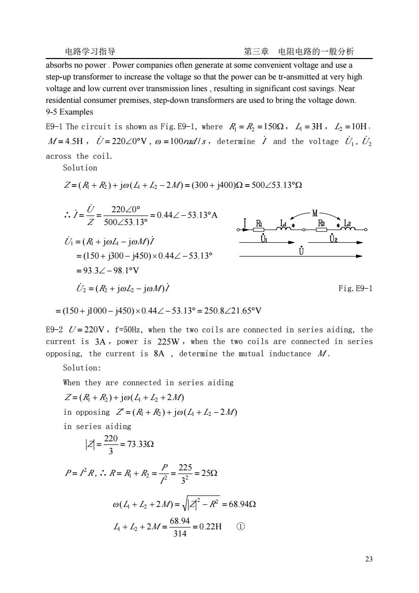
电路学习指导 第三章电阻电路的一般分析 absorbs no power.power companies often generate at some convenient voltage and use a step-up transformer to increase the voltage so that the power can be tr-ansmitted at very high voltage and low current over transmission lines,resulting in significant cost savings.Near residential consumer premises,step-down transformers are used to bring the voltage down. 9-5 Examples E9-1 The circuit is shown as Fig.E9-1,where R=R=1500,L=3H,2=10H M/=4.5H,U=22020V,@=100rad/s,determine and the voltage U,U across the coil. Solution Z=(+)+jo(L+L2-20=(300+j400)2=500∠53.132 .i= FZ500253139=04∠-53.13A 220∠0° U=(R+joL-joMi 02 =(150+j300-j450)×0.44∠-53.13° =93.3∠-98.1V i=(及+jo山-jo0/ Fig.E9-1 =(150+j1000-j450)×0.44∠-53.13°=250.8∠21.65V E9-2 U=220V,f=50Hz,when the two coils are connected in series aiding,the current is 3A,power is 225W,when the two coils are connected in series opposing,the current is 8A,determine the mutual inductance 4/. Solution: When they are connected in series aiding Z=(R+R)+jo(L+L2+20 in opposing Z=(R+R)+jo(+-2) in series aiding 14=20=7330 3 P=PR,∴R=R+R= -2m 0(山+2+2M=-R=68.942 4+6+2/=6894=022H0 314 23
电路学习指导 第三章 电阻电路的一般分析 23 absorbs no power . Power companies often generate at some convenient voltage and use a step-up transformer to increase the voltage so that the power can be tr-ansmitted at very high voltage and low current over transmission lines , resulting in significant cost savings. Near residential consumer premises, step-down transformers are used to bring the voltage down. 9-5 Examples E9-1 The circuit is shown as Fig.E9-1, where R1 = R2 =150Ω, L1 = 3H , L2 =10H , M = 4.5H , U̇ = 220∠0°V ,ω =100rad /s ,determine I ̇ and the voltage U1̇ , U2 ̇ across the coil. Solution Z = (R1 + R2 ) + jω(L1 + L2 − 2M ) = (300 + j400)Ω = 500∠53.13°Ω ∴ 0.44 53.13 A 500 53.13 220 0 = ∠ − ° ∠ ° ∠ ° = = Z U I ̇ ̇ U R L M I ̇ ̇ 1 = ( 1 + jω 1 − jω ) = (150 + j300 − j450)× 0.44∠ − 53.13° = 93.3∠ − 98.1°V U R L M I ̇ ̇ 2 = ( 2 + jω 2 − jω ) Fig.E9-1 = (150 + j1000 − j450)×0.44∠ − 53.13° = 250.8∠21.65°V E9-2 U = 220V ,f=50Hz, when the two coils are connected in series aiding, the current is 3A ,power is 225W ,when the two coils are connected in series opposing, the current is 8A , determine the mutual inductance M . Solution: When they are connected in series aiding Z = (R1 + R2 ) + jω(L1 + L2 + 2M ) in opposing Z′ = (R1 + R2 ) + jω(L1 + L2 − 2M ) in series aiding = = 73.33Ω 3 220 Z P I R2 = ,∴ = + = = = 25Ω 3 225 2 2 1 2 I P R R R ( + + 2 ) = − = 68.94Ω 2 2 ω L1 L2 M Z R 0.22H 314 68.94 L1 + L2 + 2M = = ①
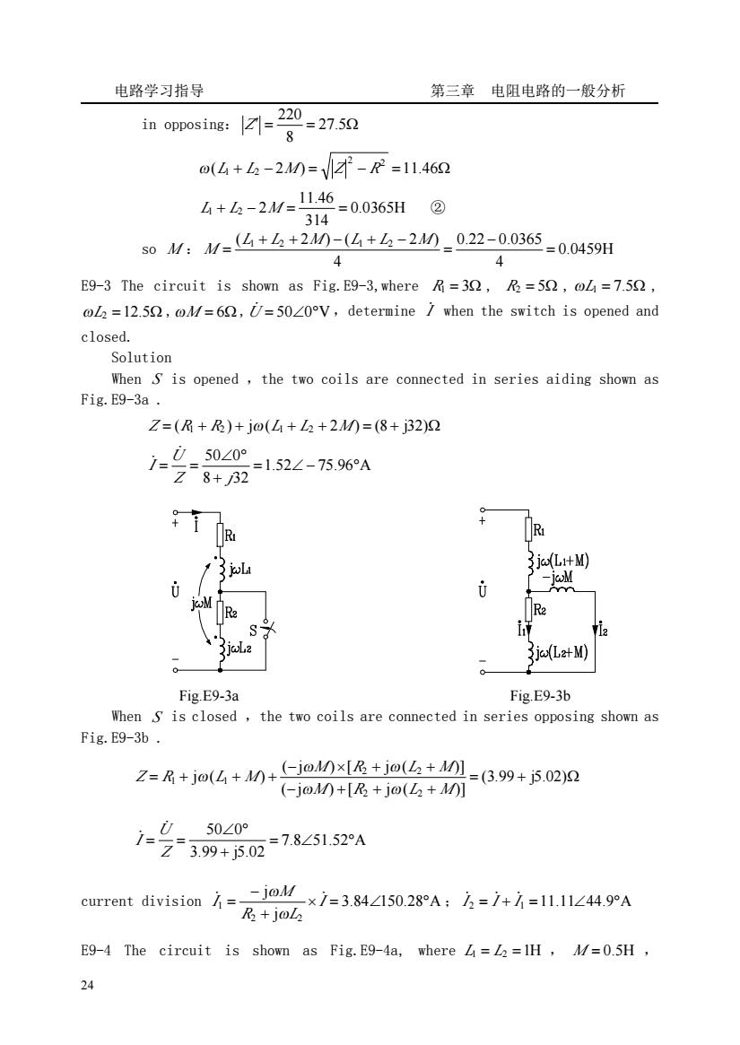
电路学习指导 第三章电阻电路的一般分析 in opposing7 (4+2-210=-R=11462 4+h-2M=1146=0.0365H@ 314 s0M:M-4+么+210=(4+4-20_02-00365-00459H 4 4 E9-3 The circuit is shown as Fig.E9-3,where R=30,R=50,@L=7.50, oL2=12.59,@M/=60,U=5020V,determine when the switch is opened and closed. Solution When S is opened,the two coils are connected in series aiding shown as Fig.E9-3a. Z=(R+及)+jo(4+L2+20=(8+j32)2 7-0-5020 28+2152∠-7596A Th8 R 13L 3jc(L+M) 3jc(L2+M) Fig.E9-3a Fig.E9-3b When s is closed,the two coils are connected in series opposing shown as Fig.E9-3b. Z=R+j(+M)+(-joMxIR+jo( =(3.99+j5.02)2 (-jo0+[R+jo(L+M] 50∠0° Z399+j502=785152A -joM current division=- ×1=3.84∠150.28A:2=1+1=11.11∠44.9°A R+jol E9-4 The circuit is shown as Fig.E9-4a,where 4=L2=IH,M/=0.5H 24
电路学习指导 第三章 电阻电路的一般分析 24 in opposing: ′ = = 27.5Ω 8 220 Z ( + − 2 ) = − =11.46Ω 2 2 ω L1 L2 M Z R 0.0365H 314 11.46 L1 + L2 − 2M = = ② so M : 0.0459H 4 0.22 0.0365 4 ( 1 2 2 ) ( 1 2 2 ) = − = + + − + − = L L M L L M M E9-3 The circuit is shown as Fig.E9-3,where R1 = 3Ω , R2 = 5Ω , ωL1 = 7.5Ω , ωL2 =12.5Ω ,ωM = 6Ω ,U̇ = 50∠0°V ,determine I ̇ when the switch is opened and closed. Solution When S is opened ,the two coils are connected in series aiding shown as Fig.E9-3a .Z = (R1 + R2 ) + jω(L1 + L2 + 2M ) = (8 + j32)Ω 1.52 75.96 A 8 32 50 0 = ∠ − ° + ∠ ° = = Z j U I ̇ ̇ Fig.E9-3a Fig.E9-3b When S is closed ,the two coils are connected in series opposing shown as Fig.E9-3b . = + Ω − + + + − × + + = + + + (3.99 j5.02) ( j ) [ j ( )] ( j ) [ j ( )] j ( ) 2 2 2 2 1 1 M R L M M R L M Z R L M ω ω ω ω ω 7.8 51.52 A 3.99 j5.02 50 0 = ∠ ° + ∠ ° = = Z U I ̇ ̇ current division 3.84 150.28 A j j 2 2 1 × = ∠ ° + − = I R L M I ̇ ̇ ω ω ; I ̇ 2 = I ̇ + I ̇ 1 =11.11∠44.9°A E9-4 The circuit is shown as Fig.E9-4a, where L1 = L2 =1H , M = 0.5H
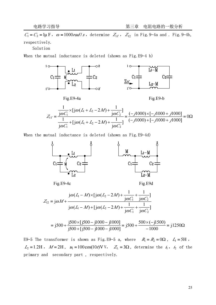
电路学习指导 第三章电阻电路的一般分析 Gi=C=lu F,=1000rad/s,determine Zir,Zi2 in Fig.9-4a and.Fig.9-4b. respectively. Solution When the mutual inductance is deleted (shown as Fig.E9-4 b) 101 02 10 M C÷ 片C2 C2 Z 1'o Fig.E9-4a Fig E9-b r.Go4+6-2n+2】 1 (-1000)×[-1000+1000] =02 1 1 loc ,(-1000)+-1000+1000 When the mutual inductance is deleted (shown as Fig.E9-4d) M C2 C C2 Fig.E9-4c Fig.E9d jo(4-Mxjo(6-2+ 1 Zi=joM+ joG joC jo(L-M0+[jo(2-20+ 0+0-0-100-j5ow+0e600-j125m =j500+j500×[j500-j100-j1001 -1000 E9-5 The transformer is shown as Fig.E9-5 a,where=R2=00,L=5H. L2=1.2H,M/=2H,=100cos(10/)V V,Z1=30,determine the of the primary and secondary part,respectively. 2
电路学习指导 第三章 电阻电路的一般分析 25 C1 = C2 =1μ F,ω =1000rad /s ,determine Z11′ , Z12 in Fig.9-4a and . Fig.9-4b, respectively. Solution When the mutual inductance is deleted (shown as Fig.E9-4 b) Fig.E9-4a Fig.E9-b = Ω − + − + − × − + = + + − + × + − + ′ = 0 ( 1000) [ 1000 1000] ( 1000) [ 1000 1000] ] j 1 [j ( 2 ) j 1 ] j 1 [j ( 2 ) j 1 2 1 2 1 2 1 2 1 11 j j j j j j C L L M C C L L M C Z ω ω ω ω ω ω When the mutual inductance is deleted (shown as Fig.E9-4d) Fig.E9-4c Fig.E9d ] j 1 j 1 j ( ) [j ( 2 ) ] j 1 j 1 j ( ) [j ( 2 ) j 1 2 1 2 1 2 1 2 12 C C L M L M C C L M L M Z M ω ω ω ω ω ω ω ω ω − + − + + − × − + + = + = Ω − × − = + + − − × − − = + j1250 1000 500 ( j1500) j500 j500 [j500 j1000 j1000] j500 [j500 j1000 j1000] j500 E9-5 The transformer is shown as Fig.E9-5 a, where R1 = R2 = 0Ω , L1 = 5H , L2 =1.2H , M = 2H , u1 =100cos(10t)V V, Z L = 3Ω , determine the i1,i2 of the primary and secondary part , respectively