
/966 Pe(x) X 2 ÷ aol=eeh=l =0 △2 (11.7) p6o小-广reew= 2-2m 312 3 (11.8) 06=2-2m/3 (11.9) So,increase in wordlength by 1 bit decreases the error by a factor of 4. 2021年2月 11
2021年2月 11 So, increase in wordlength by 1 bit decreases the error by a factor of 4

/96 Purpose of analyzing round-off noise:determine its effect at the output. If the noise variance at output is not negligible in comparison to the output signal level,the wordlength should be increased or some low-noise structure should be used. We need to compute the SNR at the output,not just the noise gain to the output. In noise analysis,we use a double-length accumulator model:rounding is performed after the (2W-1)-bit product is added. Notice:multipliers are the sources for round-off noise. 2021年2月 12
2021年2月 12 Purpose of analyzing round-off noise: determine its effect at the output. If the noise variance at output is not negligible in comparison to the output signal level, the wordlength should be increased or some low-noise structure should be used. We need to compute the SNR at the output, not just the noise gain to the output. In noise analysis, we use a double-length accumulator model: rounding is performed after the (2W-1)-bit product is added. Notice: multipliers are the sources for round-off noise
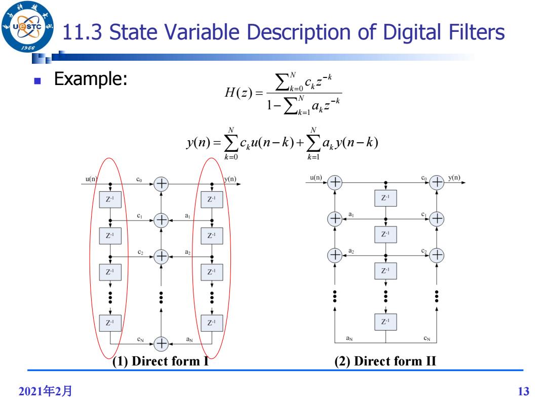
11.3 State Variable Description of Digital Filters /966 Example: H(z) 1-∑a2 0m)=立c,n-k)+立a,0n-k) u(n y(n) u(n) y(n) ● CN CN (1)Direct form (2)Direct formⅡ 2021年2月 13
2021年2月 13 11.3 State Variable Description of Digital Filters Example: (1) Direct form I (2) Direct form II N k k k N k k k a z c z H z 1 0 1 ( ) N k k N k k y n c u n k a y n k 0 1 ( ) ( ) ( )
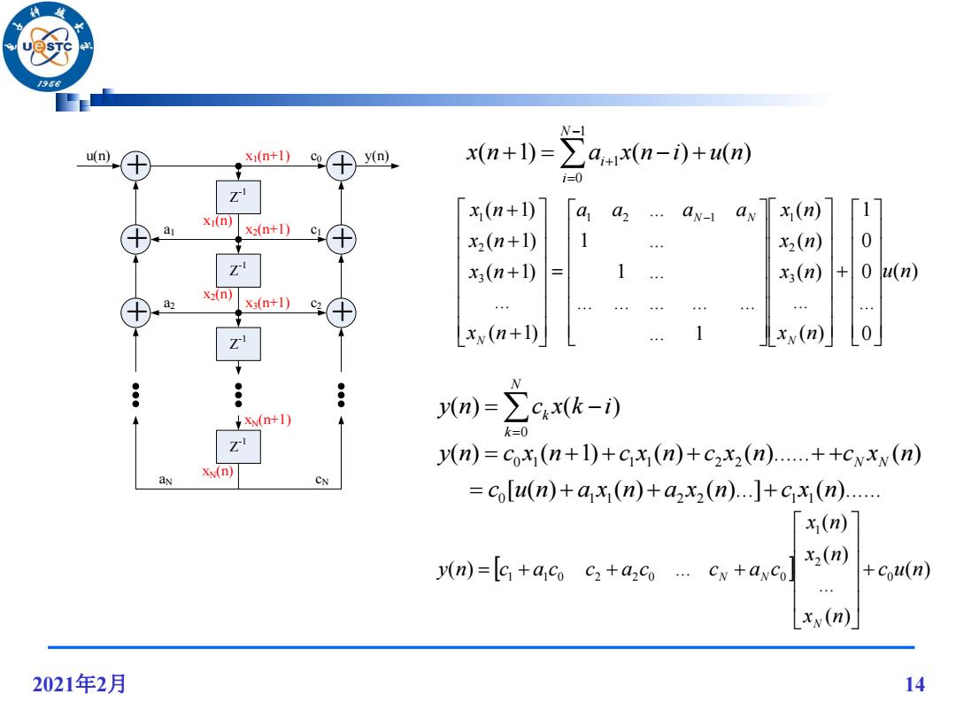
/966 u(n) x1(n+1) Co y(n) x(n+1)=) 4n-0+ml i=0 x(n+1) a, x (n) 「17 Xi(n) 2(n+1) x2(n+1) 1 x2(n) 0 x(n+1) 1 x3(n) + Ou(n) x2(n) x3(n+1) … xx(n+1) 1 xx (n) 0 g Xw(+1) m)=∑cxk-) k=0 y(n)=cox (n+1)+cx(n)+c2x2(n)......++cxxy (n) Xx(n) CN colu(n)+ax (n)+ax (n)...]+cx (n)...... x(n) x2(n) y(n)=c+a co c2+azco cx+ayco +cou(n) xx (n) 2021年2月 14
2021年2月 14 1 0 1 ( 1) ( ) ( ) N i x n ai x n i u n ( ) 0 ... 0 0 1 ( ) ... ( ) ( ) ( ) ... 1 ... ... ... ... ... 1 ... 1 ... ... ( 1) ... ( 1) ( 1) ( 1) 3 2 1 2 1 1 3 2 1 u n x n x n x n a a a a x n x n x n x n x n N N N N ( ) ( ) ... ( ) ( ) ( ) ... 0 2 1 1 1 0 2 2 0 0 c u n x n x n x n y n c a c c a c c a c N N N N k k y n c x k i 0 ( ) ( ) + + Z-1 + + Z-1 + + Z-1 Z-1 a1 a2 aN x1(n+1) x2(n+1) x3(n+1) xN(n+1) u(n) c0 y(n) c1 c2 cN x1(n) x2(n) xN(n) [ ( ) ( ) ( )...] ( )...... ( ) ( 1) ( ) ( )...... ( ) 0 1 1 2 2 1 1 0 1 1 1 2 2 c u n a x n a x n c x n y n c x n c x n c x n cN xN n

966 -Consider the signal flow graph(SFG)of an N-th order digital filter below.We can represent it in the following recursive matrix form: x(n+)=4xn)+b(n), (11.10) y(n)=c".x(n)+d.u(n) (11.11) d b u(n) y(n) (n+1) x(n) e(n) 2021年2月 15
2021年2月 15 Consider the signal flow graph (SFG) of an N-th order digital filter below. We can represent it in the following recursive matrix form: