(3)Determinationof rawmaterialtypeThe determination of raw material is related with the part geometricalshape,dimensions,mechanicalperformanceofmaterialandproductiontype, current production conditions of the workshopincludes cast steel,cast iron,cast alloy etc.The shapeof theCastingcastscanvaryfromcomplicationtosimplicity,anddimensionscanbeverylargeForginghas better mechanical performancethan castings,however.Theshapeofcrosssectioncanberound,rectangularorProfiled barotherdifferentshapes.Barsareoftenmachinedintoshaftsdishes or round shells with engine lathe, turret lathe, orautomaticorsemiautomaticlathe,andthedimensionscanvaryfromsmalltomedium size.butitsthicknessislimitedwithinaWeldingfor complicated and large parts can be welded from profiled baror forged parts, but the welded part performs badly in someEngineeringused widely in mechanical manufacturing in recent years.Itsplasticshapecanvaryfrom simpletocomplicated,andthedimensionaccuracyishigh,butmechanicalperformanceisweak
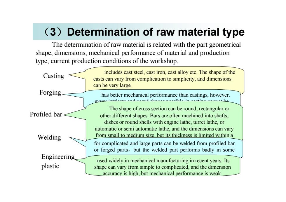
(3)Determination of raw material type The determination of raw material is related with the part geometrical shape, dimensions, mechanical performance of material and production type, current production conditions of the workshop. Casting includes cast steel, cast iron, cast alloy etc. The shape of the casts can vary from complication to simplicity, and dimensions can be very large. Forging has better mechanical performance than castings, however. many intricate and cored shapes possible in casting cannot be forged. Profiled bar The shape of cross section can be round, rectangular or other different shapes. Bars are often machined into shafts, dishes or round shells with engine lathe, turret lathe, or automatic or semi automatic lathe, and the dimensions can vary from small to medium size. but its thickness is limited within a range. Welding for complicated and large parts can be welded from profiled bar or forged parts,but the welded part performs badly in some Engineering respects. plastic used widely in mechanical manufacturing in recent years. Its shape can vary from simple to complicated, and the dimension accuracy is high, but mechanical performance is weak
In large batch or largequantity production,highly precise andefficient manufacturing methodsforraw material areoften used.such as die casting, precise casting, die forging, cold punching ,andpowdermetallurgy.Allthesemethodsmaketherawmaterial shapeclose to that of the final design part. Therefore, the labor required inmetalremovalcanbegreatlyreduced,sometimesevennometalremoval isneeded.Not onlycanthematerial be saved,but also themechanical manufacturingcost canbereduced.In single or small batch production, sand casting withwooden mould or free deformed forging are often used. Therefore,the accuracy is low, the cost is high, the acceptance ratio is low, andthe labor engaged in metal removal is large
In large batch or large quantity production, highly precise and efficient manufacturing methods for raw material are often used, such as die casting, precise casting, die forging, cold punching ,and powder metallurgy. All these methods make the raw material shape close to that of the final design part. Therefore, the labor required in metal removal can be greatly reduced , sometimes even no metal removal is needed. Not only can the material be saved, but also the mechanical manufacturing cost can be reduced. In single or small batch production, sand casting with wooden mould or free deformed forging are often used. Therefore, the accuracy is low, the cost is high, the acceptance ratio is low, and the labor engaged in metal removal is large
(4)Process route planningIt includes selectionofmountingsurfaceandmachiningmethod.classificationofprocessphases,sequencingtheoperations,determiningthedegree of operation distribution, arrangement of hot working or inspectionandotherauxiliaryoperations.(5)selectionofmachinetools,technicalequipment(includingcuttingtools,fixtures and inspection tools) and auxiliary tools for each operation.(6) selection ofmetal removal, operationdimensionsand tolerances foreachoperation(7)Selection of metal cutting parameters and standard operation times 。(8)technical economical analysis(9)formtheprocessfile
(4) Process route planning It includes selection of mounting surface and machining method, classification of process phases, sequencing the operations, determining the degree of operation distribution, arrangement of hot working or inspection and other auxiliary operations . (5)selection of machine tools, technical equipment (including cutting tools, fixtures and inspection tools) and auxiliary tools for each operation. (6)selection of metal removal, operation dimensions and tolerances for each operation (7)Selection of metal cutting parameters and standard operation times 。 (8)technical economical analysis (9)form the process file
1.3 selection of positioningreference(datum)positioning reference is used to define the position of otherpoints,lines or surfaces of the part are called the positioning referencedatum.1.3.1 Classification of positioning referencePositioningreference can beclassified intotwo categories accordingtoapplicationpurpose返回
1.3 selection of positioning reference(datum) positioning reference is used to define the position of other points, lines or surfaces of the part are called the positioning reference datum. 1.3.l Classification of positioning reference Positioning reference can be classified into two categories according to application purpose
1.3.1.1 Design referenceThepoints, lines or surfaces that areused bydesignersto determinethedimensionsorrelativepositionsof otherpoints,lines or surfacesarecalledthedesignreference.Forexample,inFig43asectionCisthedesign reference of side A and B, the center line OO is the designreference of the cylindrical surfaces @ D and d, and the center point OisthedesignreferenceofsurfaceE(b)(a) moviemovieFig43(c)movie
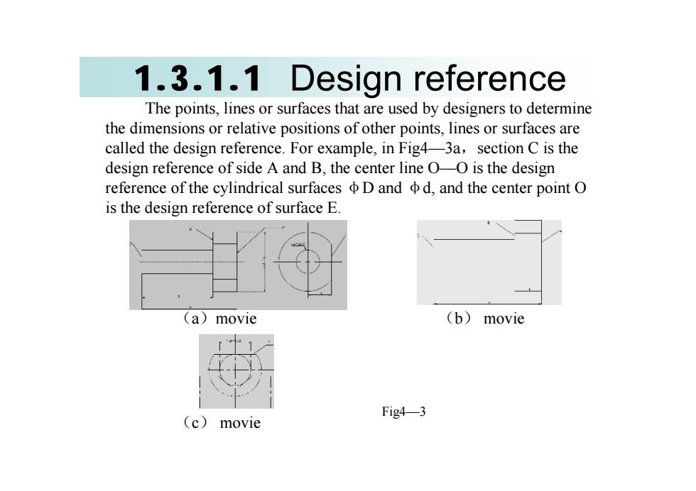
1.3.1.1 Design reference The points, lines or surfaces that are used by designers to determine the dimensions or relative positions of other points, lines or surfaces are called the design reference. For example, in Fig4—3a,section C is the design reference of side A and B, the center line O—O is the design reference of the cylindrical surfaces φD and φd, and the center point O is the design reference of surface E. (a)movie (b) movie (c) movie Fig4—3