Chapter3 MachiningAccuracyAbstractThe machining accuracy of machine parts is the quality foundation of the whole machine.It is usuallymeasured with two indices: machining accuracy and surface quality and their value size will directly affecttheperformanceand life of thewholemachine.This chaptermainly involvesthemachiningaccuracyThe basic concepts,factors that are related with the machining accuracy, the comprehensive analysis ofmachining errors,and themethods of raising themachining accuracy arediscussed in this chapter3.1 Basicconceptofmachining accuracy3.1.1 Machining accuracy and machining errorMachining accuracy:The degree of the practical dimensions after machining conforms to the desiredgeometrical parameters.The higher the degree conforms, the higher the machining accuracy.Machining error:The degree of the practical dimensions after machining deviates from the desiredgeometrical parameters.The size of the machining error denotes the size of the machining accuracy.“"Machining accuracy"and"Machining error"are two different concepts to evaluatethe accuratedegreeofthepart geometries.Inproduction practice,theaccuracyis ensured by controllingthemachiningerrororactiveadaptingmethod3.1.2ThemethodtostudythemachiningaccuracyThere are two methods to study the machining accuracy.One is the single factor analysis method, inwhich the machining accuracy is analyzed by calculation, experiment or inspection so as to decide thesinglefactors influencinglawto thesingleerror.Another oneis the statistic method,in whichthestatistical theoryisusedtoprocesstheinspecteddata ofa batchofworkpiecefromthepracticesoastocontroltheprocessrunninginnormal condition.Thesetwomethodsareoftenused togetherinpractice.Generally.thestatisticmethod is first usedtofind out the law of the error, and judge the causes, then factor analysis method is used to find out thekeyfactors which influence the machining accuracy.3.2FactorsaffectingthemachiningaccuracyPartmachininghappensintheprocessing systemcomposedofmachinetools,fixtures,cuttingtooland workpiece.All thefactors in the PrincipkeerrerClaification of eriginal errorsystemthatmaycausemachiningerrorsAdinuztment crrsrare called the original errors. TheSulp LmTexistence of the original errors makesBeforeMichire Ipol enprmachiringthe positional or motional relationshipFixture errerSlaliccmordeviated from its desired state, andCutingtoolmauerorbrings about the machining error. If theOriaianlexistedbeforeoriginalerrorsDelionrualion riderfarcerror原machining,or in another word, it isIn machiningrhaunel deforutation始实兰:Tyiamiccnmcaused without the cutting force, it isutingtool rccalledthestaticprocessing error,otherwise, it is called the dynamicSelnrlicnhyiuriershesAftermachiniprocess error.Inspectioncrtor
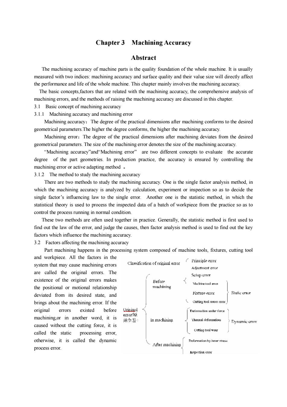
Chapter 3 Machining Accuracy Abstract The machining accuracy of machine parts is the quality foundation of the whole machine. It is usually measured with two indices: machining accuracy and surface quality and their value size will directly affect the performance and life of the whole machine. This chapter mainly involves the machining accuracy. The basic concepts,factors that are related with the machining accuracy, the comprehensive analysis of machining errors, and the methods of raising the machining accuracy are discussed in this chapter. 3.1 Basic concept of machining accuracy 3.1.1 Machining accuracy and machining error Machining accuracy:The degree of the practical dimensions after machining conforms to the desired geometrical parameters.The higher the degree conforms, the higher the machining accuracy. Machining error:The degree of the practical dimensions after machining deviates from the desired geometrical parameters. The size of the machining error denotes the size of the machining accuracy. “Machining accuracy”and“Machining error” are two different concepts to evaluate the accurate degree of the part geometries. In production practice, the accuracy is ensured by controlling the machining error or active adapting method 。 3.1.2 The method to study the machining accuracy There are two methods to study the machining accuracy. One is the single factor analysis method, in which the machining accuracy is analyzed by calculation, experiment or inspection so as to decide the single factor’s influencing law to the single error. Another one is the statistic method, in which the statistical theory is used to process the inspected data of a batch of workpiece from the practice so as to control the process running in normal condition. These two methods are often used together in practice. Generally, the statistic method is first used to find out the law of the error, and judge the causes, then factor analysis method is used to find out the key factors which influence the machining accuracy. 3.2 Factors affecting the machining accuracy Part machining happens in the processing system composed of machine tools, fixtures, cutting tool and workpiece. All the factors in the system that may cause machining errors are called the original errors. The existence of the original errors makes the positional or motional relationship deviated from its desired state, and brings about the machining error. If the original errors existed before machining,or in another word, it is caused without the cutting force, it is called the static processing error, otherwise, it is called the dynamic process error
Weight deformationDeformationGeometricundercuttingaccuracyoftheforcemachinetoolThermal deformationControl system accuracyWorkpieceTool wearaccuracyLocationandclampingaccuracy3.2.1ErrorofmachiningprincipleMachiningprinciplereferstotheformingprinciple of thesurface ontheworkpiece.Theerrorofmachiningprincipleiscausedbysimilarcuttingmotionofformingorsimilarcuttingedgegeometry.Thepurpose is to simplify the design and manufacturing of the machine tool and cutting tool, reduce themanufacturing cost, raise the production efficiency and facilitate the use.3.2.2ErrorofthemachinetoolError ofthe machine tool refers to the manufacture error,setup error and wear come fromthe machinetoolwithout cutting force3.2.2.1 spindle rotational error(1)concept of spindle rotational errorTheoretically,thepositionoftherotationalaxisofthespindleinthespaceisfixed,orinanotherword.the instant speed is zero.But in practice,therearea lotof factors influencetheposition of the spindleandmake the spindle position change instantly.We call the maximum floating value in the sensitive direction ofthe error the rotational error ofthe spindle.There are three types of spindle rotational error, shown below:A4(b)(a)Fig.1 the three types of the spindle error of the machine tool(a) Pure radial jump (b) pure axial jump (c) pure angular movePure radial jump : The practical axis is parallel to the desired axis, but jump in constant amplitudePure axial jump :The practical axis moves along the desired axis with constant amplitude.Pureangularmove:Thepracticalaxismoves inclinedtothedesiredaxiswithaconstantamplitudeandthejointpointkeeps constant(2)influenceofthespindleerroronmachiningaccuracyDifferent rotational error of the spindle has different influence on the machining accuracy,even thesamerotationalerrorhasdifferentinfluencewhenthemachiningmethodisdifferent.shownasFig.3.5,3.63.7、3.8andtable3.1
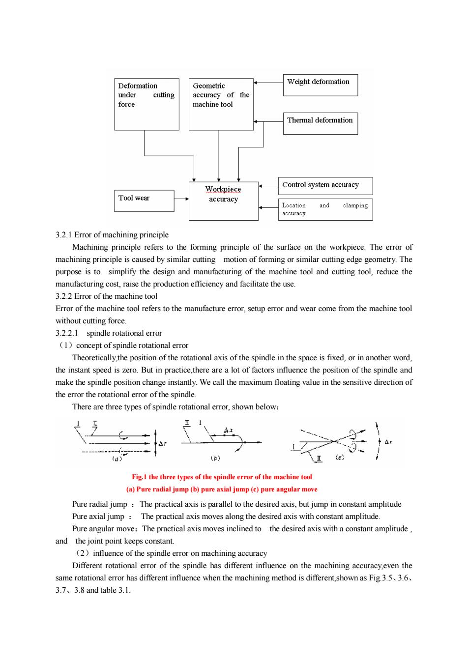
3.2.1 Error of machining principle Machining principle refers to the forming principle of the surface on the workpiece. The error of machining principle is caused by similar cutting motion of forming or similar cutting edge geometry. The purpose is to simplify the design and manufacturing of the machine tool and cutting tool, reduce the manufacturing cost, raise the production efficiency and facilitate the use. 3.2.2 Error of the machine tool Error of the machine tool refers to the manufacture error, setup error and wear come from the machine tool without cutting force. 3.2.2.1 spindle rotational error (1)concept of spindle rotational error Theoretically,the position of the rotational axis of the spindle in the space is fixed, or in another word, the instant speed is zero. But in practice,there are a lot of factors influence the position of the spindle and make the spindle position change instantly. We call the maximum floating value in the sensitive direction of the error the rotational error of the spindle. There are three types of spindle rotational error, shown below: Pure radial jump :The practical axis is parallel to the desired axis, but jump in constant amplitude Pure axial jump : The practical axis moves along the desired axis with constant amplitude. Pure angular move:The practical axis moves inclined to the desired axis with a constant amplitude , and the joint point keeps constant. (2)influence of the spindle error on machining accuracy Different rotational error of the spindle has different influence on the machining accuracy,even the same rotational error has different influence when the machining method is different,shown as Fig.3.5、3.6、 3.7、3.8 and table 3.1. Fig.1 the three types of the spindle error of the machine tool (a) Pure radial jump (b) pure axial jump (c) pure angular move
化华...车H实快间H.WR(a) Turning influenced byradial jump(b) Boring influenced by radial jumpEnd surface influenced byAngular moveBoringinfluencedbyAngularmovementerrorTable1influence of the spindle error on the surfaces underdifferent machining method十床上#设床上代七辑回转设荐的基木彩式谢萨内.外同鼎2L尚地径向斯动影摄小大彩时土识光中百#保控“业设无婴明果距识差光E电轴间印动方工品务正监实室可托费汉选您明教小欢识纯拍晓供动因生片保学“向设3.2.2.2 Error of the guidewayThe guideway of the machine tool is the main reference datum for the relative position and motion ofthemain componentswiththeothercomponents.Itwill influencethemachiningaccuracydirectly(1)linearerrorintheverticalplaneRLThe linear error in the vertical planeaof theguideway on ahorizontal latheorexternal cylindrical grinding machinecanbeomitted becausetheerror is inthe non-sensitive direction which is△R△ Z? / 2R. But for planegrinding machine or gantry planer, the(a)error will directly reflect on theFig.3.9The linearerror of the guidewayworkpiece.(2)linear error in horizontal planeFor a horizontal lathe,the linear error in horizontal plane is in the sensitive direction, shown as
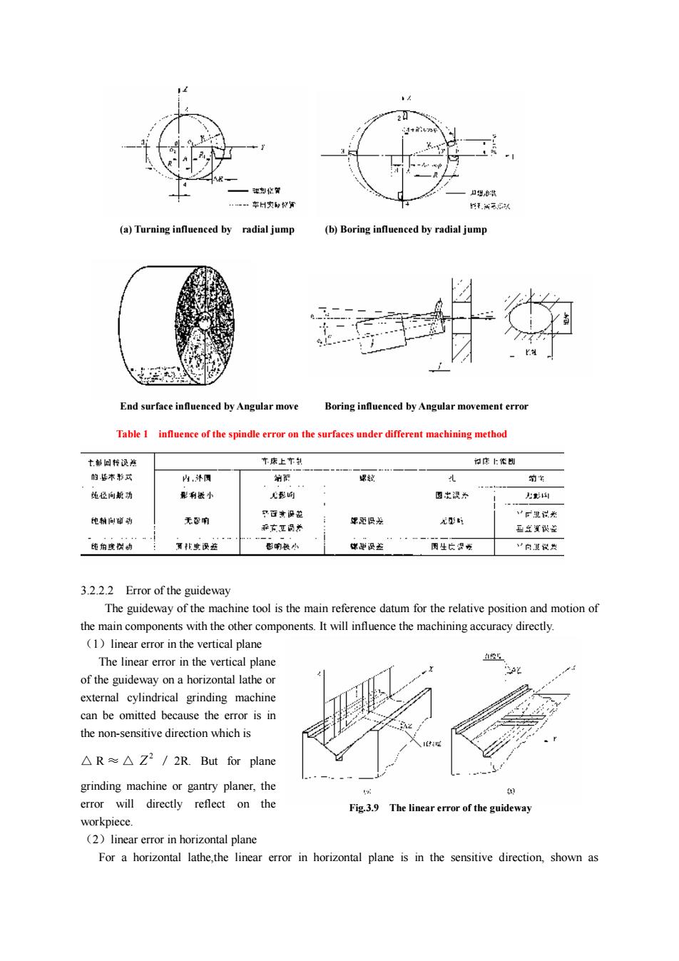
3.2.2.2 Error of the guideway The guideway of the machine tool is the main reference datum for the relative position and motion of the main components with the other components. It will influence the machining accuracy directly. (1)linear error in the vertical plane The linear error in the vertical plane of the guideway on a horizontal lathe or external cylindrical grinding machine can be omitted because the error is in the non-sensitive direction which is △ R ≈ △ 2 Z / 2R. But for plane grinding machine or gantry planer, the error will directly reflect on the workpiece. (2)linear error in horizontal plane For a horizontal lathe,the linear error in horizontal plane is in the sensitive direction, shown as (a) Turning influenced by radial jump (b) Boring influenced by radial jump End surface influenced by Angular move Boring influenced by Angular movement error Table 1 influence of the spindle error on the surfaces under different machining method Fig.3.9 The linear error of the guideway
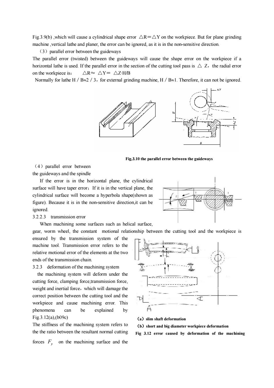
Fig.3.9(b),which will cause a cylindrical shape error R=Y on the workpiece.But for plane grindingmachinevertical lathe and planer, the error can be ignored, as it is in the non-sensitive direction(3)parallelerrorbetweentheguidewaysThe parallel error (twisted) between the guideways will cause the shape error on the workpiece if ahorizontal lathe is used If the parallel error in the section ofthe cutting tool pass is Z,the radial erroron the workpiece is:AR~△Y=AZ·H/BNormally for lathe H/ B=2 /3, for external grinding machine, H / B=1. Therefore, it can not be ignored.Fig.3.10theparallelerrorbetweentheguideways(4)parallelerrorbetweenthe guideways and the spindleIf the error is in the horizontal plane, the cylindricalsurface will have taper error;Ifit is in the vertical plane, thecylindrical surface will become a hyperbola shape(shown asfigure). Because it is in the non-sensitive direction,it can beignored.3.2.2.3transmissionerrorWhenmachiningsomesurfaces suchashelical surfacegear, worm wheel, the constantmotional relationship between the cutting tool and the workpiece isensured by the transmission system of themachine tool Transmission error refers to therelativemotional erroroftheelements atthetwoends ofthetransmission chain.3.2.3deformationofthemachiningsystemthe machining system will deform under thecuttingforce,clampingforce,transmissionforce,weight and inertial force, which will damage thecorrect position between the cutting tool and theHworkpiece and causemachining error.ThisAbeexplainedbyphenomenacanFig.3.12(a),(b09c)(a)slim shaftdeformationThe stiffness of themachining systemrefersto(b) short andbig diameter workpiece deformationthe the ratio between the resultant normal cuttingFig 3.12 error caused by deformation of the machiningforces F.onthemachiningsurfaceandthe
Fig.3.9(b) ,which will cause a cylindrical shape error △R=△Y on the workpiece. But for plane grinding machine ,vertical lathe and planer, the error can be ignored, as it is in the non-sensitive direction. (3)parallel error between the guideways The parallel error (twisted) between the guideways will cause the shape error on the workpiece if a horizontal lathe is used. If the parallel error in the section of the cutting tool pass is △ Z,the radial error on the workpiece is: △R≈ △Y= △Z·H/B Normally for lathe H/B»2/3,for external grinding machine, H/B»1. Therefore, it can not be ignored. (4)parallel error between the guideways and the spindle If the error is in the horizontal plane, the cylindrical surface will have taper error;If it is in the vertical plane, the cylindrical surface will become a hyperbola shape(shown as figure). Because it is in the non-sensitive direction,it can be ignored. 3.2.2.3 transmission error When machining some surfaces such as helical surface, gear, worm wheel, the constant motional relationship between the cutting tool and the workpiece is ensured by the transmission system of the machine tool. Transmission error refers to the relative motional error of the elements at the two ends of the transmission chain. 3.2.3 deformation of the machining system the machining system will deform under the cutting force, clamping force,transmission force, weight and inertial force,which will damage the correct position between the cutting tool and the workpiece and cause machining error. This phenomena can be explained by Fig.3.12(a),(b09c) The stiffness of the machining system refers to the the ratio between the resultant normal cutting forces Fy on the machining surface and the Fig.3.10 the parallel error between the guideways (a)slim shaft deformation (b)short and big diameter workpiece deformation Fig 3.12 error caused by deformation of the machining
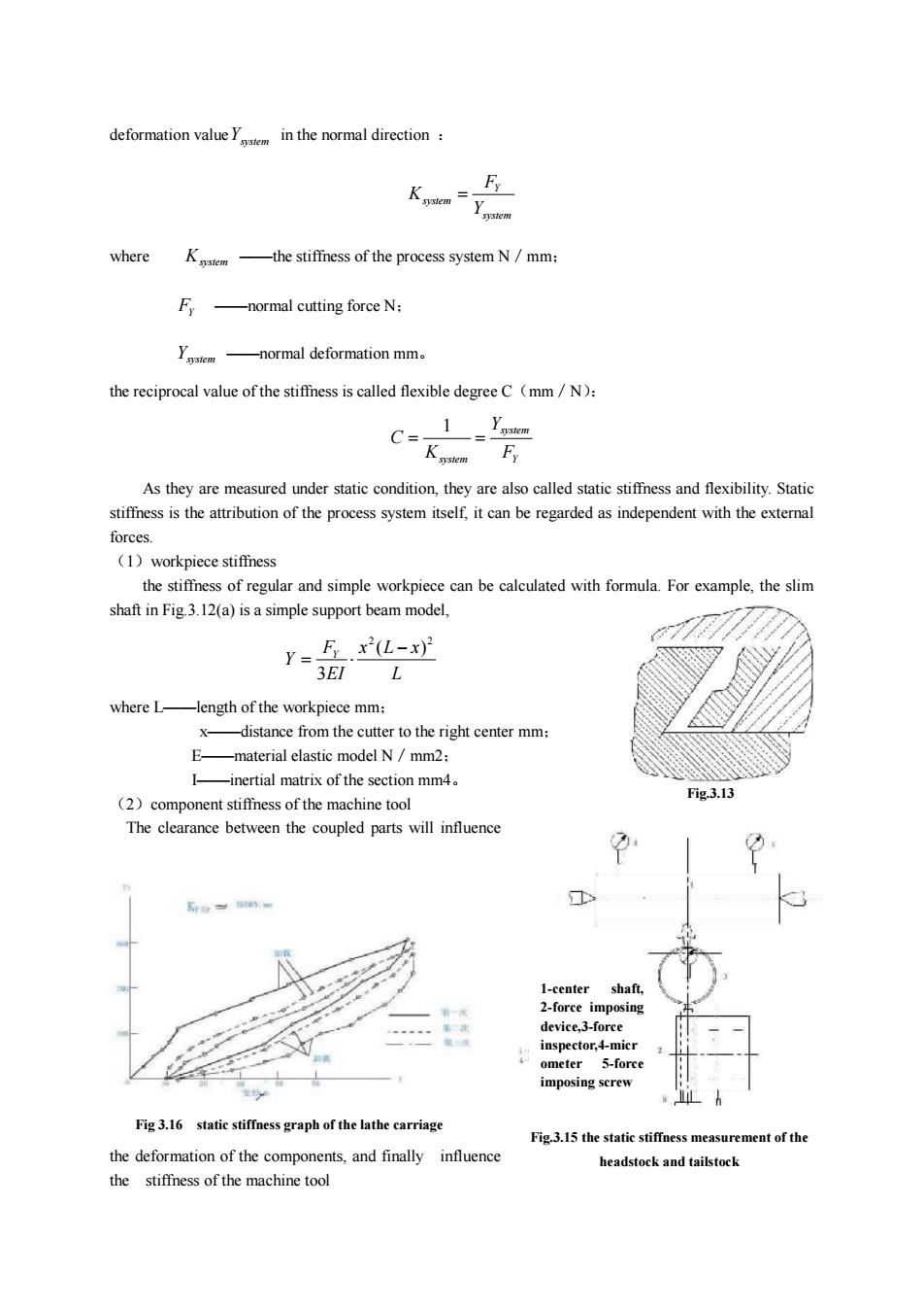
deformation valueYinthenormal direction:FwhereK.-the stiffness of the process system N / mm;F,normal cutting force N-normaldeformationmm。the reciprocal valueofthe stiffness is calledflexibledegreeC(mm/N)Ysem1CKgstemFyAs they are measured under static condition,theyare also called static stiffness and flexibility.Staticstiffness is the attribution of the process system itself, it can be regarded as independent with the externalforces.(1)workpiecestiffnessthe stiffnessof regular and simpleworkpiece canbe calculatedwithformula.For example,the slimshaft in Fig.3.12(a) is a simple support beam model,Fx(L-x)?Y=3EILwhere L--lengthoftheworkpiecemm;distancefromthecuttertotherightcentermm;F.-materialelasticmodelN/mm2;-inertialmatrixofthesectionmm4Fig.3.13(2)componentstiffnessofthemachinetoolThe clearance between the coupled parts will influenceK1-centershaft,2-force imposingdevice,3-forceinspector,4-micrometer5-forceimposing screwFig3.16static stiffness graph of thelathe carriageFig.3.15 the static stiffness measurement of thethe deformation of the components, and finallyinfluenceheadstock and tailstockthestiffness ofthemachinetool
deformation valueYsystem in the normal direction : system Y system Y F K = where Ksystem ——the stiffness of the process system N/mm; FY ——normal cutting force N; Ysystem ——normal deformation mm。 the reciprocal value of the stiffness is called flexible degree C(mm/N): Y system system F Y K C = = 1 As they are measured under static condition, they are also called static stiffness and flexibility. Static stiffness is the attribution of the process system itself, it can be regarded as independent with the external forces. (1)workpiece stiffness the stiffness of regular and simple workpiece can be calculated with formula. For example, the slim shaft in Fig.3.12(a) is a simple support beam model, L x L x EI F Y Y 2 2 ( ) 3 - = × where L——length of the workpiece mm; x——distance from the cutter to the right center mm; E——material elastic model N/mm2; I——inertial matrix of the section mm4。 (2)component stiffness of the machine tool The clearance between the coupled parts will influence the deformation of the components, and finally influence the stiffness of the machine tool Fig.3.13 Fig.3.15 the static stiffness measurement of the headstock and tailstock 1-center shaft, 2-force imposing device,3-force inspector,4-micr ometer 5-force imposing screw Fig 3.16 static stiffness graph of the lathe carriage