Chapter2Thedesignprincipleof jigs and fixturesabstractIn order to fulfill themachining requirement of a certain job,a relatively accurate positionof theworkpiece in a machine tool in relation to the cutting tool duringthe metal cutting movementmust be ensured.Thefollowing three conditions mustbe satisfied when fulfilling such apracticalfunction, which are(1) the accurate position ofa batch of workpieces in relation to the jigs or fixtures;(2)the accurateposition of thejigs or fixturesinrelationtothemachinetool;(3)theaccurateposition ofthe cutting tool in relation to the jigs orfixtures. In this chapter, themain attention is directedto the accurate positioning of workpieces in jigs or fixtures.Thepositioning ofworkpiecesinmachine tools isindirectly achieved through jigs or fixtures.Single screw jigs or fixtures2.1Introduction of jigs or fixtures Positioning :in order to ensure the accuracy andraise the efficiency, jigs or fixtures should be used toensure the accurate position of the workpiece inrelation to the machine tool.Clamping:Inordertoensurethepositionofthelocationunderexternal force,a clampingforcemustbeimposedontheworkpiece,"SetupThe comprehensive procedure ofpositioning andclamping+Jigs or fixtures :The technological equipment to fulfllthe procedure of set up2.1.1 Classification ofjigs or fixturesJigsorfixtures canbeclassified intotwocategoriesaccordingtotheirgeneral purpose,whichare:Themostwidelyusedjigsorfixturesingeneral-purpose jigsmechanicalmanufacture,complicated structureorfixturesJigs orfixtures-Arespeciallydesignedandmadeforonejob,orspecial purpose jigsmade of somestandard elements, has a more simple,orfixturescompact, and easytouse operational structure
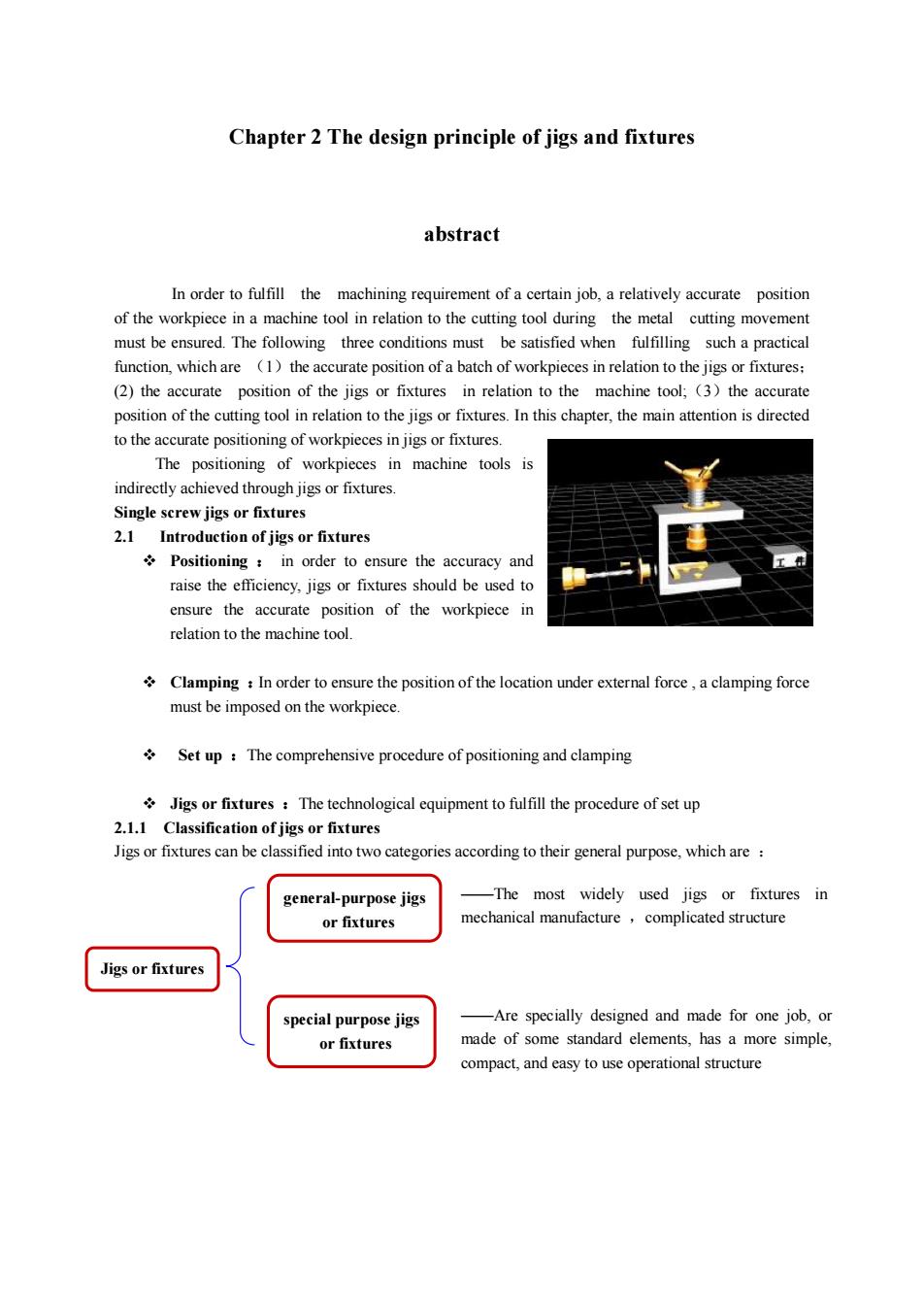
Chapter 2 The design principle of jigs and fixtures abstract In order to fulfill the machining requirement of a certain job, a relatively accurate position of the workpiece in a machine tool in relation to the cutting tool during the metal cutting movement must be ensured. The following three conditions must be satisfied when fulfilling such a practical function, which are (1)the accurate position of a batch of workpieces in relation to the jigs or fixtures; (2) the accurate position of the jigs or fixtures in relation to the machine tool;(3)the accurate position of the cutting tool in relation to the jigs or fixtures. In this chapter, the main attention is directed to the accurate positioning of workpieces in jigs or fixtures. The positioning of workpieces in machine tools is indirectly achieved through jigs or fixtures. Single screw jigs or fixtures 2.1 Introduction of jigs or fixtures v Positioning : in order to ensure the accuracy and raise the efficiency, jigs or fixtures should be used to ensure the accurate position of the workpiece in relation to the machine tool. v Clamping :In order to ensure the position of the location under external force , a clamping force must be imposed on the workpiece. v Set up :The comprehensive procedure of positioning and clamping v Jigs or fixtures :The technological equipment to fulfill the procedure of set up 2.1.1 Classification of jigs or fixtures Jigs or fixtures can be classified into two categories according to their general purpose, which are : Jigs or fixtures general-purpose jigs or fixtures special purpose jigs or fixtures ——The most widely used jigs or fixtures in mechanical manufacture ,complicated structure ——Are specially designed and made for one job, or made of some standard elements, has a more simple, compact, and easy to use operational structure
2.1.2The function and components of jigs or fixturesexamplesto explainthefunction and components ofjigs or fixtures: 1-quick change bush 2-guide bush3-drillplate2-open cushion2-screwnut6-location pin7-body ofthe jigWecanknowfromtheexample 2.1.2.1The function of jigs or fixtures:(1)Reducethenonproductivetime,and raisetheproductionefficiency;(2)maintainthestabilityofmachiningaccuracy;(3)enlarge the application scope ofmachine tools(4)release the working stress, and ensure secure production2.1.2.2 The components of jigs or fixtures:(1)the location element,shown in Fig,rhombus post7;(2)clamping deviceshown inFigthescrewnut5、openwasher4;(3) setting element , shown in Fig thedrilling bush 1 ;(4)bodyof jigs orfixtures:(5)other elements and devices,Dependingon the practical requirement, some jigs orfixtures have a dividing head, and the milling fixturemust have a positionkey,etc2.2The location of the workpiece2.2.1Theoretical positioningofa solidin space(isostatism)It is well known that a perfect solid can be positioned in space by sixand three rotationalparameters, normally three moveable parametersparametersIn Fig.2-2, six degrees of freedom of a free soliddenoted by X口(1)movefollowaxesX,Fig.2-2 Six degrees of公口denotedby(2)movefollowaxesY,freedom ofan objectdenotedbyZ口(3)movefollowaxesZ(4) rotate around axes X, denoted by X口rotate around axes Y, denoted by Y口(5)by 2口(6)denotedrotatearoundaxesZ
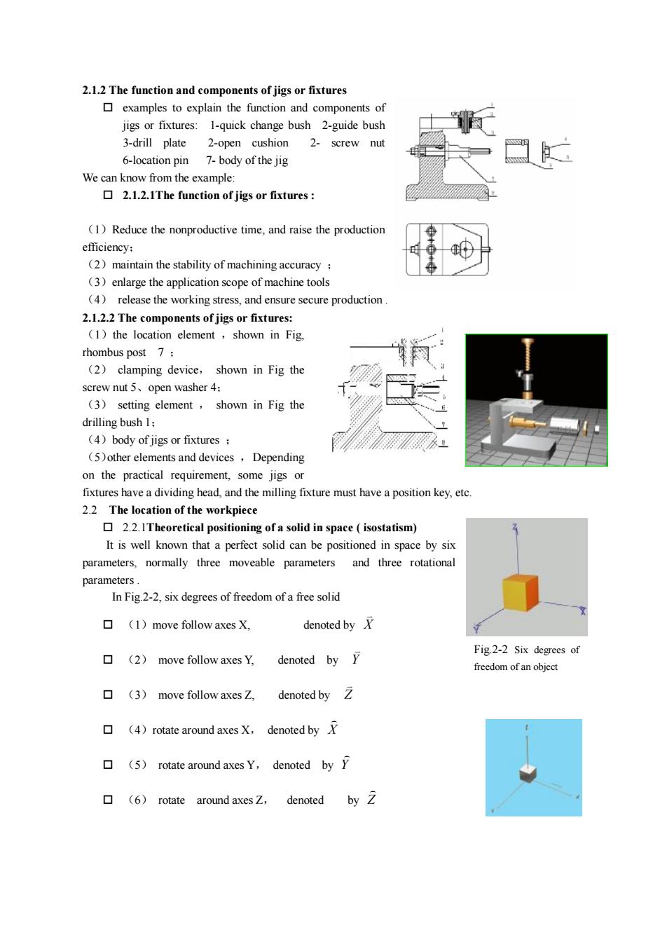
2.1.2 The function and components of jigs or fixtures o examples to explain the function and components of jigs or fixtures: 1-quick change bush 2-guide bush 3-drill plate 2-open cushion 2- screw nut 6-location pin 7- body of the jig We can know from the example: o 2.1.2.1The function of jigs or fixtures : (1)Reduce the nonproductive time, and raise the production efficiency; (2)maintain the stability of machining accuracy ; (3)enlarge the application scope of machine tools (4) release the working stress, and ensure secure production . 2.1.2.2 The components of jigs or fixtures: (1)the location element ,shown in Fig, rhombus post 7 ; (2) clamping device, shown in Fig the screw nut 5、open washer 4; (3) setting element , shown in Fig the drilling bush 1; (4)body of jigs or fixtures ; (5)other elements and devices ,Depending on the practical requirement, some jigs or fixtures have a dividing head, and the milling fixture must have a position key, etc. 2.2 The location of the workpiece o 2.2.1Theoretical positioning of a solid in space ( isostatism) It is well known that a perfect solid can be positioned in space by six parameters, normally three moveable parameters and three rotational parameters . In Fig.2-2, six degrees of freedom of a free solid o (1)move follow axes X, denoted by X v o (2) move follow axes Y, denoted by Y v o (3) move follow axes Z, denoted by Z v o (4)rotate around axes X, denoted by X ) o (5) rotate around axes Y, denoted by Y ) o (6) rotate around axes Z, denoted by Z ) Fig.2-2 Six degrees of freedom of an object
The six points location principleThis principle was first proposed by physicists of the nineteenth century such as Lord Kelven,Maxwell,Curie,Michelson and others who needed to position objects exactly for their measuringinstruments.An equivalent way ofdefining isostatism isto saythatthereactionforces on the sixpointsofcontact can be determined by the six equations of classical statics.In Fig.2-4, a workpiece has a definite location in space bycanceling its sixdegrees of freedom In the field of mechanical engineering, this method ofcanceling the degrees of freedom to locate a part, calledXthe six points location principle-Concept:Fig.2-4sixdegreesof freedomComplete location :all the sixdegrees offreedom havecancelledforaworkpiecebeen cancelledIncomplete location : not all the 6 degrees of freedom have been cancelled,but still satisfy therequirement.Redundant location:twolocation elements have both cancelled the samedegree of freedomfora workpiece. Insufficient location : the number of location points is less than the degrees of freedom whichmustbe cancelled,the workpiece is insufficiently located.(0)0LCRedundant locationand elimination
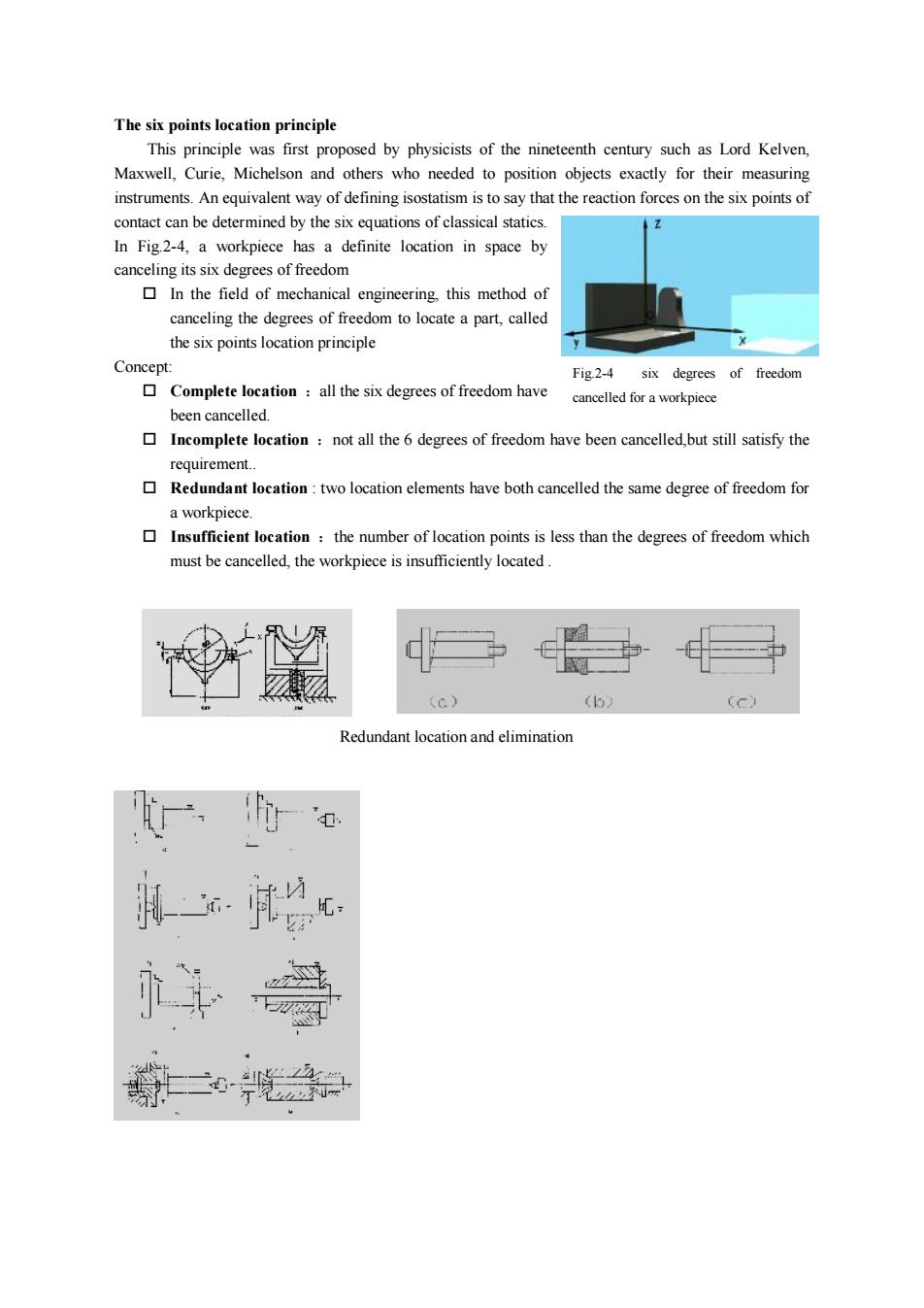
The six points location principle This principle was first proposed by physicists of the nineteenth century such as Lord Kelven, Maxwell, Curie, Michelson and others who needed to position objects exactly for their measuring instruments. An equivalent way of defining isostatism is to say that the reaction forces on the six points of contact can be determined by the six equations of classical statics. In Fig.2-4, a workpiece has a definite location in space by canceling its six degrees of freedom o In the field of mechanical engineering, this method of canceling the degrees of freedom to locate a part, called the six points location principle Concept: o Complete location :all the six degrees of freedom have been cancelled. o Incomplete location :not all the 6 degrees of freedom have been cancelled,but still satisfy the requirement. o Redundant location : two location elements have both cancelled the same degree of freedom for a workpiece. o Insufficient location :the number of location points is less than the degrees of freedom which must be cancelled, the workpiece is insufficiently located . Fig.2-4 six degrees of freedom cancelled for a workpiece Redundant location and elimination
2.2.2Thelocation elementsThe distribution of the location elements in jigs or fixtures must conform to the six-pointprinciple on the one hand. On the other hand, the distribution envelope of the location elementsshould be as large as possible so as to make the weight ofthe workpiece and the cuttingforce fallwithin the area formed by the support points.2.2.2.1The main technical specifications and usual material usedfor thelocation elements. Concerning thetechnical specification:firstly,sufficient locationaccuracy and lowroughnessvalues must be ensured. Secondly, a definite wear resistance, hardness and stiffness must beensured. Concerning the material used for the location elements: generally, there are two kinds ofcommonly usedmaterial:(1)mildsteel:suchas20or20Cr,HRC55~65;(2)highcarbon steel such as T7、T8、T102.2.2.2classifyoflocationelementssupportpostadjustahlelocatinnelementssupport plateFised laaionelenentslocation pitlotafiunelementscenterdus shattAnyllarysmpportelerirn.shaped blockfloating locationsupport2.2.2.2Fixed location elements(1)cylindrical supportpost(支撑钉)taD(eThere are two types,one is used in rough machining with round top, another one is used infinishmachining with flattop.Sometimes, thetop ismade with pattern to increasethe friction, but only used inside face.Why?
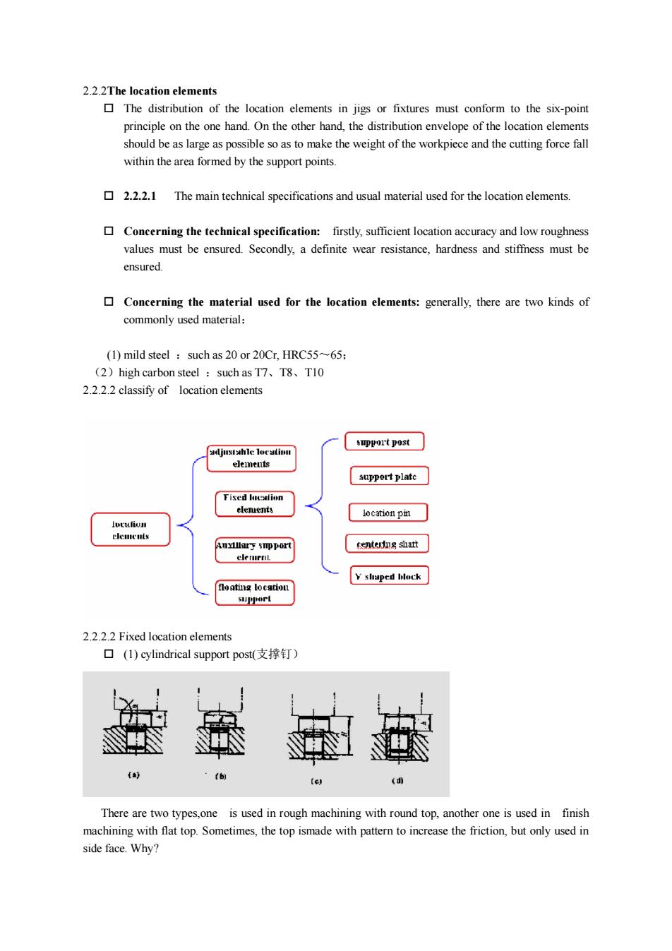
2.2.2The location elements o The distribution of the location elements in jigs or fixtures must conform to the six-point principle on the one hand. On the other hand, the distribution envelope of the location elements should be as large as possible so as to make the weight of the workpiece and the cutting force fall within the area formed by the support points. o 2.2.2.1 The main technical specifications and usual material used for the location elements. o Concerning the technical specification: firstly, sufficient location accuracy and low roughness values must be ensured. Secondly, a definite wear resistance, hardness and stiffness must be ensured. o Concerning the material used for the location elements: generally, there are two kinds of commonly used material: (1) mild steel :such as 20 or 20Cr, HRC55~65; (2)high carbon steel :such as T7、T8、T10 2.2.2.2 classify of location elements 2.2.2.2 Fixed location elements o (1) cylindrical support post(支撑钉) There are two types,one is used in rough machining with round top, another one is used in finish machining with flat top. Sometimes, the top ismade with pattern to increase the friction, but only used in side face. Why?
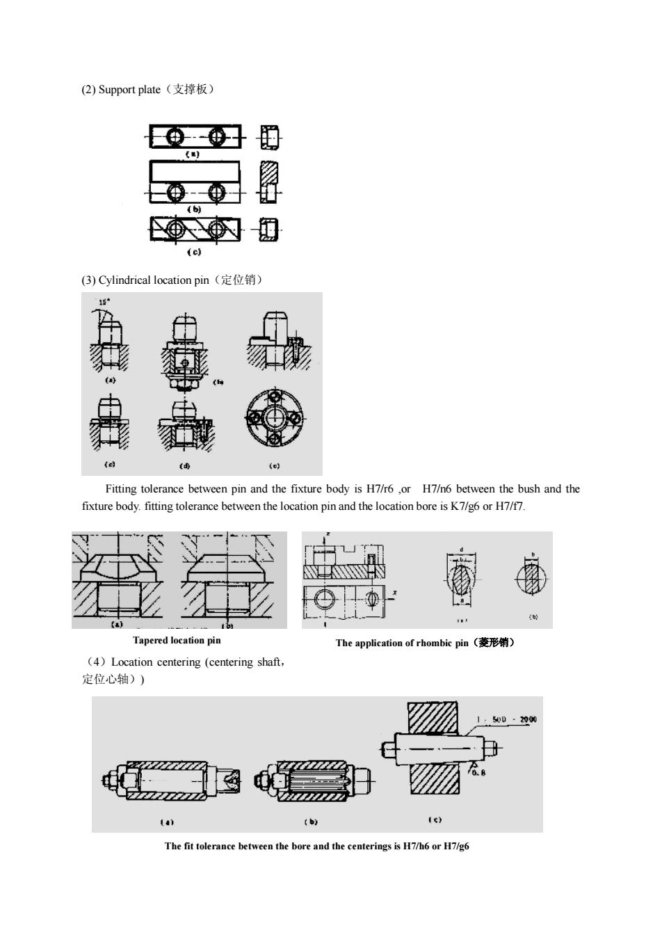
(2)Supportplate(支撑板)0(e)(3)Cylindricallocationpin(定位销)EFitting tolerance between pin and the fixture body is H7/r6 ,or H7/n6 between the bush and thefixturebody.fitting tolerancebetweenthelocationpin and thelocation bore isK7/g6orH7/f7Tapered location pinTheapplication of rhombic pin(菱形销)(4)Location centering (centering shaft,定位心轴))SDD:-2000bCThefittolerancebetweenthebore and the centerings is H7/h6 orH7/g6
(2) Support plate(支撑板) (3) Cylindrical location pin(定位销) Fitting tolerance between pin and the fixture body is H7/r6 ,or H7/n6 between the bush and the fixture body. fitting tolerance between the location pin and the location bore is K7/g6 or H7/f7. (4)Location centering (centering shaft, 定位心轴)) Tapered location pin The application of rhombic pin(菱形销) The fit tolerance between the bore and the centerings is H7/h6 or H7/g6