section C is the design reference of side A and B, the center line OO is the design reference of thecylindrical surfaces D and d, and the center point O is the design reference of surface E(b)a)(c)4.3.1ProcessreferenceThereferencewhichis used intheprocess of operation orassembling is calledtheprocessreferenceor manufacturing reference. According to its application purpose, it can be further classified into 4subcategories(1)OperationreferenceIn engineering drawings,the points,lines or surfaces that areused to determine the operationdimensions or positions relative to the machined surface are called the operation reference.(2)PositioningreferenceThe positioning reference is defined as the points, lines or surfaces whichareused to determinethe location of points,lines or surfacesthat are to bemachined. The process that determines the location is called positioningAsa surface isusuallyusedaspositioningreference,positioningreferenceis also called positioning surface, and the sign“V"is usually used to representit, with the bottom directed towards the positioning surface.as shown in Fig.1-4(3)inspectionreferencethe points, lines or surfaces which are used as a reference to inspect theFig.1-4 represent methodlocationof machined surfacesarecalledthe inspectionreferenceof positioning surfaceIn most cases, thedesignreference is used as the inspection reference.(4)assembling referenceIn the process of assembling,the points, lines or surfaces which are used as a reference to determinethe locations of the parts or components relativeto the product are called the assembling reference.Forexample,whenagear is tobe installed ona shaft,its hole is used as theassemblingreference,When the spindle box is to be installed onto a machine bed, the base of the box becomes theassemblingreference.1.3.2 The clamping method and means to obtain the desired accuracy4-3-2-1The clamping() positioning and clamping by direct locationWhenputtingtheworkpiecedirectly onthemachinebed,theoperatorcanlocatethemachinedsurfacebyusinga micrometerinspection instrument, marking dish or straight rules to adjust andFig.1-5 setup by locatingfind the desired machiningposition relativeto the cutting tool.It is usually used in single or small batch type production, or inthe condition of high accuracy machining requirement to relative position when it is hard to meet byafixture
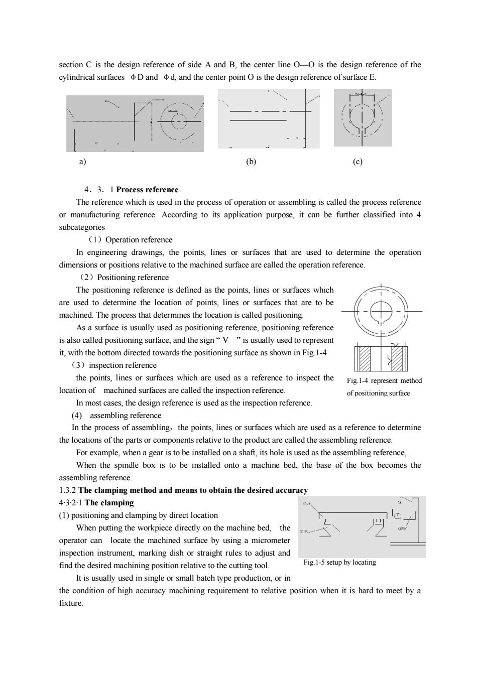
section C is the design reference of side A and B, the center line O—O is the design reference of the cylindrical surfaces φD and φd, and the center point O is the design reference of surface E. 4.3.1 Process reference The reference which is used in the process of operation or assembling is called the process reference or manufacturing reference. According to its application purpose, it can be further classified into 4 subcategories (1)Operation reference In engineering drawings, the points, lines or surfaces that are used to determine the operation dimensions or positions relative to the machined surface are called the operation reference. (2)Positioning reference The positioning reference is defined as the points, lines or surfaces which are used to determine the location of points, lines or surfaces that are to be machined. The process that determines the location is called positioning. As a surface is usually used as positioning reference, positioning reference is also called positioning surface, and the sign “ V ” is usually used to represent it, with the bottom directed towards the positioning surface.as shown in Fig.1-4 (3)inspection reference the points, lines or surfaces which are used as a reference to inspect the location of machined surfaces are called the inspection reference. In most cases, the design reference is used as the inspection reference. (4) assembling reference In the process of assembling,the points, lines or surfaces which are used as a reference to determine the locations of the parts or components relative to the product are called the assembling reference. For example, when a gear is to be installed on a shaft, its hole is used as the assembling reference, When the spindle box is to be installed onto a machine bed, the base of the box becomes the assembling reference. 1.3.2 The clamping method and means to obtain the desired accuracy 4·3·2·1 The clamping (1) positioning and clamping by direct location When putting the workpiece directly on the machine bed, the operator can locate the machined surface by using a micrometer inspection instrument, marking dish or straight rules to adjust and find the desired machining position relative to the cutting tool. It is usually used in single or small batch type production, or in the condition of high accuracy machining requirement to relative position when it is hard to meet by a fixture. a) (b) (c) Fig.1-4 represent method of positioning surface Fig.1-5 setup by locating
(2)Clampingaccordingtothepre-markedtrailofoutlineThiskind ofclampingmethod is widelyused in singleor small batch typeproduction,and theerror ofthe operation itself exists, the clamping accuracy is low, usually in the range 0.2~0.5mm.Before the work is machined, the outline of the surfacetobemachined on the rawmaterial isdrawnbeforehand, then located and clamped on themachine tool according to the pre-drawn linesWhen drawing the outline to be machined, sufficient metal removal must be ensured.(3)ClampedwithafixtureThis kind of methodis convenient, fast, accurate and stable. It is widely used in batch type productionand largequantityproductionFor example, in Fig.1-1, it is an operation of machining a key in a stepped shaft.For some parts in small batches,such as the connecting rod or crank shafts,even though the batchquantity is not large, some special fixtures are still required in order to meet the specific machiningrequirement.Fig1-6 the setup of the keymachined operationObviously,the relativepositional accuracyamong different surfaces inmechanical machining,suchas parallel, the perpendicular and coaxial degrees of accuracy, can be obtained with the above clampingmethod using several clamping steps,andalso it canbeobtainedbyarranging thedifferent surfaces tobemachined inthe same clamping.Thesetwomethodsarebothcommonlyused to obtaintherelativepositional accuracy in mechanical machining.1.3.2.2Methods ofobtainingthedimensional accuracy(1)Methods to obtain the dimensional accuracy in mechanical machiningTrial cutting method :a tiny part of the surface to be machined is pre-cut, and the dimensions areinspected. Then,proper adjustment is made according to the desired requirement, and try cutting is triedagain. This process is usually repeated twice or three times to meet the final need. Finally, the wholesurface is machined according to the final adjustment@Setting dimension method :The accuracy of the machined surface is ensured by applying a cuttingtool with the required accuracy, such as a reamer, twist drill or core drill.③Adjustmethodthe accuracy is ensured by the cutting route setting device or pre-adjusted carriages to get the correctpositionofthecuttingtool inrelationwiththemachinetoolorfixture?Automaticcontrolmethodsome special automatic control devices are used to ensure the accuracy.The specific methods include1) automatic inspection- the inspection device is integrated into the machine tool. When the
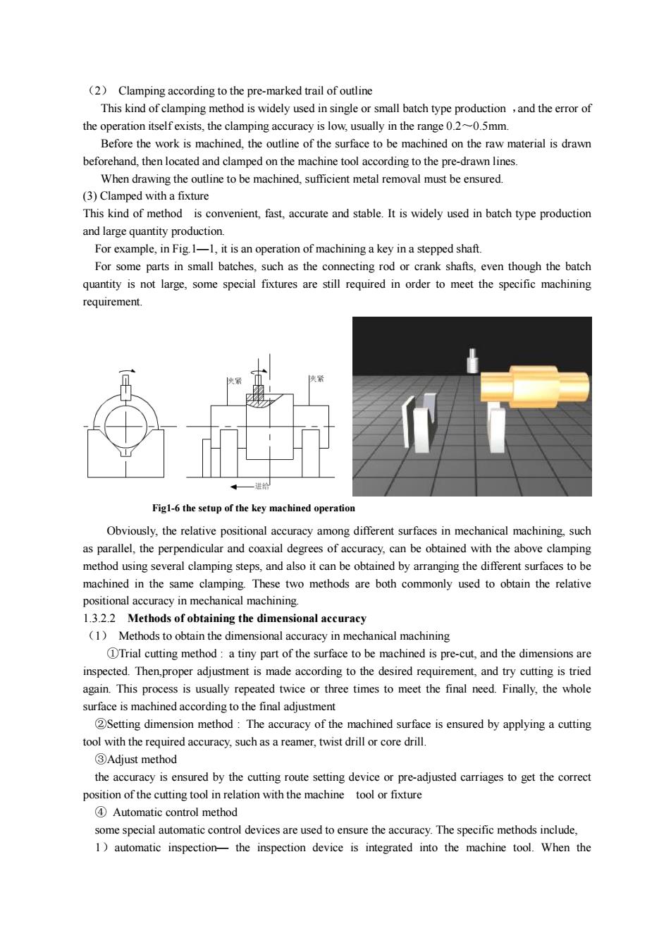
(2) Clamping according to the pre-marked trail of outline This kind of clamping method is widely used in single or small batch type production ,and the error of the operation itself exists, the clamping accuracy is low, usually in the range 0.2~0.5mm. Before the work is machined, the outline of the surface to be machined on the raw material is drawn beforehand, then located and clamped on the machine tool according to the pre-drawn lines. When drawing the outline to be machined, sufficient metal removal must be ensured. (3) Clamped with a fixture This kind of method is convenient, fast, accurate and stable. It is widely used in batch type production and large quantity production. For example, in Fig.1—1, it is an operation of machining a key in a stepped shaft. For some parts in small batches, such as the connecting rod or crank shafts, even though the batch quantity is not large, some special fixtures are still required in order to meet the specific machining requirement. Obviously, the relative positional accuracy among different surfaces in mechanical machining, such as parallel, the perpendicular and coaxial degrees of accuracy, can be obtained with the above clamping method using several clamping steps, and also it can be obtained by arranging the different surfaces to be machined in the same clamping. These two methods are both commonly used to obtain the relative positional accuracy in mechanical machining. 1.3.2.2 Methods of obtaining the dimensional accuracy (1) Methods to obtain the dimensional accuracy in mechanical machining ①Trial cutting method : a tiny part of the surface to be machined is pre-cut, and the dimensions are inspected. Then,proper adjustment is made according to the desired requirement, and try cutting is tried again. This process is usually repeated twice or three times to meet the final need. Finally, the whole surface is machined according to the final adjustment ②Setting dimension method : The accuracy of the machined surface is ensured by applying a cutting tool with the required accuracy, such as a reamer, twist drill or core drill. ③Adjust method the accuracy is ensured by the cutting route setting device or pre-adjusted carriages to get the correct position of the cutting tool in relation with the machine tool or fixture ④ Automatic control method some special automatic control devices are used to ensure the accuracy. The specific methods include, 1)automatic inspection— the inspection device is integrated into the machine tool. When the Fig1-6 the setup of the key machined operation