
PeiLi-ran on wireless synchronization device in superficial Research on wireless synchronization device in superficial seismic exploration Zhang Lin-hang.Pei Li-ran,Sun Zi-chao,Wang Cong (College of instrumentation and electrical engineering.Jilin University,Changchun 130061.China) Abstract-In order to better solve the time synchronization problem of shallow seismic prospecting signal acquisition.Put forward a data acquisition ystem of shallow seismic exploration based on wireless network.t controller as the main ,Use AD7705 chip with low powerc mption and high resolution to realize collection ,Choose nRF24L01 set up wireless network ,According to the characteristics of modulus conversion unit and MCU Design the power module and the voltage stabilizing circuit to realize accurate fexible power supply.By determining the real-time data of different transmission distance,Use seismograph for time compensation thus realize data acquisition vnchronization Solving the complex wiring and svachronizatio s when the conditions for exploration.realizing ow-power.portable and synchronization function in the shallow seismic exploration.Tests show that the ystem powe ance is 94m,and trans n delay time is less than 1.87 us Key words-Instrument and meter technology;wireless Synchronous;prediction model;superficial seismic exploration data acquisition:Analog-to-digital conversion;Wireless synchronization con sumption is the key of system design.The mor INTRODUCTION mature and widely used in wirele communication are mainly GPRs,WiFi,Imote2,Zigbee,ultra wideband SHALLOW seismic exploration is the use impulse,but can meet the design requirements of the of special detection equipment,record the artificial few such as the GPRS network,although can meet the excitation seismic reflec on and refraction,wave travel communication distance requirements,but the in order to analyze and speed is not meet the judge ofa geophysical method formation interface of requirements of rapid transmission of large amounts of geotechnical and geological structurel1.2].Shallow seismic data the:Although WiFi can meet the seismic exploration instruments are precision and key transmission speed requirements,but the real equipment for the most shallow seismic prospecting3] environment of radio interference too much can not And the synchronization of ata guarantee the accuracy of the data meet the wireless technology has become an wireless synchronous but ismainly important index to measure the shallow seismic applied to speed8 Zigbee sensor network are slower and prospecting instrument.The measurement precision of not through a barrier];Ultra wideband pulse wireless time synchronization directly influences the quality of transmission distance.low power consumption and poor anti-interference ability data and low ccuracy[10 alysis and inversio of seismic wave 11]Integrated simple and portable,low power With the poor and the exploration of shallow seismic wireless synchronization requirements,this study adopts exploration environment of the expansion5.the cable nRF24L01 wireless module to realize wireless telemetry seismic instrument mainstream in some degree transmission based on detecting and combined with the it is difficult to meet the actual needs and requirements of AD7705 analog to digital conversion using strain sensor must] it not only has the Radio telemetry seismic instrument not ony reduces the hardware,good stability:software algorithm is fast and field work burden,but also avoid the inherent large line efficient,the design has important significance for crosstalk,antenna interference,frequency interference. seismic data acquisition in shallow layer and wireless so synchronization wireless portable[7],low power synchronization 19
Pei Li-ran etc.: Research on wireless synchronization device in superficial seismic exploration 19 Research on wireless synchronization device in superficial seismic exploration Zhang Lin-hang, Pei Li-ran, Sun Zi-chao, Wang Cong (College of instrumentation and electrical engineering, Jilin University, Changchun 130061, China) Abstract—In order to better solve the time synchronization problem of shallow seismic prospecting signal acquisition, Put forward a data acquisition system of shallow seismic exploration based on wireless network.It uses AT89C51 micro-controller as the main controller,Use AD7705 modulus conversion chip with low power consumption and high resolution to realize data collection ,Choose nRF24L01 set up wireless network ,According to the characteristics of modulus conversion unit and MCU ,Design the power module and the voltage stabilizing circuit to realize accurate flexible power supply.By determining the real-time data of different transmission distance ,Use seismograph for time compensation thus realize data acquisition synchronization .Solving the complex wiring and synchronization problems when the conditions for exploration,realizing low-power,portable and synchronization function in the shallow seismic exploration.Tests show that the system power consumption is 2500mW ,the wireless transmission distance is 94m, and transmission delay time is less than 1.87μs. Key words—Instrument and meter technology; wireless Synchronous; prediction model; superficial seismic exploration; data acquisition; Analog-to-digital conversion; Wireless synchronization . INTRODUCTION SHALLOW seismic exploration is the use of special detection equipment , record the artificial excitation seismic reflection and refraction , wave travel time,amplitude , waveform , in order to analyze and judge of a geophysical method formation interface of geotechnical and geological structure[1、2] . Shallow seismic exploration instruments are precision and key equipment for the most shallow seismic prospecting[3] . And the synchronization precision of data acquisition and wireless transmission technology has become an important index to measure the shallow seismic prospecting instrument. The measurement precision of time synchronization directly influences the quality of seismic observation records, is required for seismic data analysis and inversion of seismic wave valuable data[4]. With the poor and the exploration of shallow seismic exploration environment of the expansion[5], the cable telemetry seismic instrument mainstream in some degree , it is difficult to meet the actual needs, and requirements of shallow seismic exploration instrument must be light[6] . Radio telemetry seismic instrument not only reduces the field work burden, but also avoid the inherent large line crosstalk , antenna interference , frequency interference , so synchronization, wireless , portable[7] , low power consumption is the key of system design.The more mature and widely used in wireless communication are mainly GPRs , WiFi , Imote2 , Zigbee , ultra wideband impulse , but can meet the design requirements of the few , such as the GPRS network , although can meet the communication distance requirements , but the communication speed is low,can not meet the requirements of rapid transmission of large amounts of seismic data the ; Although WiFi can meet the transmission speed requirements , but the real environment of radio interference too much , can not guarantee the accuracy of the data ; Imote2 can meet the wireless synchronous but complex protocol and is mainly applied to speed[8] Zigbee sensor network are slower and not through a barrier[9] ; Ultra wideband pulse wireless transmission distance , low power consumption and poor anti-interference ability , data and low accuracy[10、 11].Integrated simple and portable , low power and wireless synchronization requirements , this study adopts nRF24L01 wireless module to realize wireless transmission based on detecting, and combined with the AD7705 analog to digital conversion using strain sensor , it not only has the real-time detection ability , and simple hardware , good stability; software algorithm is fast and efficient , the design has important significance for seismic data acquisition in shallow layer and wireless synchronization

The English Proceedings of the College of Instrumentation Electrical Engineering.Jilin University,in the Second Half of 2013 instrument cono system,the hammer source signal is I THE STRUCTURE OF THE OVERALLSYSTEM DESIGN received by the detector data synchronous transmission system,through the wireless transmission to the The system consists of detector data synchronous acquisition terminal of the wireless synchronous transmission system and acquisition terminal of the receiving and processing system,start the seismograph ceiving and proc ssing syst em of io The overall structure wo parts,the shallow layer seismic exploration,seismic diagram is shown in figure I Wireles ower-supp The LMI1173.3 The LMI1173.3 module; regulalor circu Detector data synchr receiving and pr cessing system FigIThe overall struture diagram Detector data wireless svnchronous transmission affect the acquisition to the acc racy of the data The system will han pressure senso circuit is converted to analog voltage n figure 2 signal,using A/D 16 to improve the signal acquisition A/D data processing precision,synchronous signal picked up he AT89C5 ion st controlle by the wireless data transmission module hased or is the main par of the ens measured data time synchronization reference power-supply module acquisition terminal of the wireless synchronous receiving and processing system to receive the data Fig2Data acquisition system the nRF24L01 wireless transmi Acquisition systen consists of the exactly same data r,analog digital conversion module with AD7705 wireless transmission.wireless transmission relay and as the core and taking AT89C51 as the core ofthe receiving delay resulting in svynchronization main controller error.timing meter or oscilloscope through the 2.I Design ofA/D comversion circuit calculation of a specific delay ime ource signal hasa weak signal,amplitudei instrument synchroniza adjustment using the softwar strong compensation method the error synchronizing signal signal-to-noise ratio,the signal frequency is low,so the to target. A/D circuit should have high gain,high input impedance,high CMRR characteristic. 2 DESIGN OF DATAACQUISITION MODULE Acquisition system usinga small hammer as simulation source using strain type pressure Hammer source signal acquisition module plays converts the analog signal into voltage signal through the an important role in the whole system.Amplification A/D conversion circuit,digital.The A/D conversion circuit,the anti-interference ability and stability directly circuit using AD7705 chip,it has high resolution,wide 20
期 The English Proceedings of the College of Instrumentation & Electrical Engineering, Jilin University, in the Second Half of 2013 20 1THE STRUCTURE OF THE OVERALL SYSTEM DESIGN The system consists of detector data synchronous transmission system and acquisition terminal of the wireless synchronous receiving and processing system of two parts , the shallow layer seismic exploration , seismic instrument control system , the hammer source signal is received by the detector data synchronous transmission system , through the wireless transmission to the acquisition terminal of the wireless synchronous receiving and processing system , start the seismograph began data acquisition . The overall structure block diagram is shown in figure 1 . Detector data wireless synchronous transmission system will hammer source signal through the strain type pressure sensor circuit is converted to analog voltage signal , using A/D 16 to improve the signal acquisition , data processing precision , synchronous signal picked up by the wireless data transmission module based on nRF24L01 transmission in digital mode is more accurate , is the main part of the ensure the test signal and then measured data time synchronization reference ; acquisition terminal of the wireless synchronous receiving and processing system to receive the data wireless transmission system transmits the same step by using the nRF24L01 wireless data transmission module in exactly the same data , the wireless transmission, wireless transmission , relay and receiving delay , resulting in synchronization error , timing meter or oscilloscope through the calculation of a specific delay time , seismic instrument synchronization adjustment using the software compensation method , the error synchronizing signal to target . 2 DESIGN OF DATA ACQUISITION MODULE Hammer source signal acquisition module plays an important role in the whole system. Amplification circuit, the anti-interference ability and stability directly affect the acquisition to the accuracy of the data . The source signal acquisition module block diagram is shown in figure 2 . Strain type pressure transducer The AT89C51 host controller power-supply module; A/D conversion unit Acquisition system consists of the strain sensor , analog digital conversion module with AD7705 as the core and taking AT89C51 as the core of the main controller . 2.1 Design of A/D conversion circuit Hammer source signal has a weak signal , amplitude is small , strong electromagnetic interference , low signal-to-noise ratio , the signal frequency is low , so the A/D circuit should have high gain , high input impedance , high CMRR characteristic . Acquisition system using a small hammer as simulation source , using strain type pressure sensor converts the analog signal into voltage signal through the A/D conversion circuit , digital . The A/D conversion circuit using AD7705 chip , it has high resolution , wide Fig. 2 Data acquisition system Fig.1 The overall structure diagram
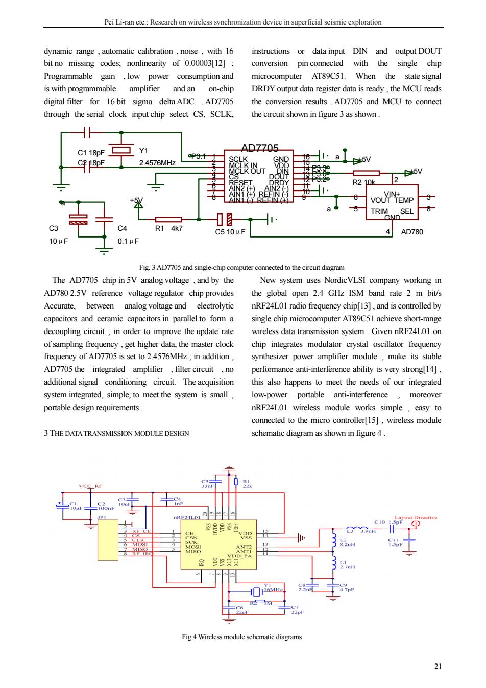
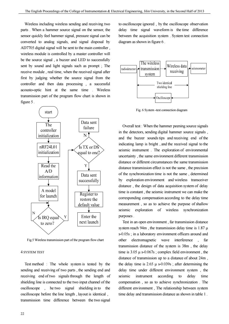
Pei Li-ran ete.:Research on wireless synchronization device in superficial seismic exploration dynamic range,automatic calibration,noise,with 16 instructions or data input DIN and output DOUT bit no missing codes:nonlinearity of 0.0000312] conversion pin connected with the single chip Programmable gain,low power consumption and microcomputer AT89C51.When the state signal is with programmable amplifier and an on-chir DRDYoutput data register data is ready,the MCU reads digital filter for 16 bit sigma deltaADC AD7705 the conv ersion results.AD7705 and MCU to connect input chip select CS.SCLK the circuit shown in figure3as shown C1 18pE Y1 AD7705 CP 18pF 2.4576MHz VOUTNEMP a TR坠nsL 0.1uF AD780 Fig.3 AD7705 and single-chip computer connected to the circuit diagram The AD7705 chip in 5V analog voltage,and by the New system uses NordicVLSI company working in AD78025V reference voltage regulator chip provides the global open 24 GHz ISM band rate 2 m bit/s Accurate analog voltage and nRF24L01 radio frequency chip[13],and is controlled by capacitors and eramic apacitors in paralleto form single chip microcomputer AT89C5 short-range decoupling circuit in order to improve the update rate wireless data transmission system.Given nRF24L01 on of sampling frequency,get higher data.the master clock chip integrates modulator crystal oscillator frequency frequency of AD7705 is set to 2.4576MHz;in addition, synthesizer power amplifier module,make its stable AD7705 the integrated amplifier filter circuit no performance anti-interference ability is very strongl141 thisas happens to meet the needs of our integrat system integrated,simple,to meet the system is sma low-power portable anti-interference moreover portable design requirements. nRF24LOI wireless module works simple,easy to connected to the micro controller[15],wireless module 3 THE DATA TRANSMISSION MODULE DESIGN schematic diagram as shown in figure 4. 22 Fig.4 Wireless module schematic diagram
Pei Li-ran etc.: Research on wireless synchronization device in superficial seismic exploration 21 dynamic range , automatic calibration , noise , with 16 bit no missing codes; nonlinearity of 0.00003[12] ; Programmable gain , low power consumption and is with programmable amplifier and an on-chip digital filter for 16 bit sigma delta ADC . AD7705 through the serial clock input chip select CS, SCLK, instructions or data input DIN and output DOUT conversion pin connected with the single chip microcomputer AT89C51. When the state signal DRDY output data register data is ready , the MCU reads the conversion results . AD7705 and MCU to connect the circuit shown in figure 3 as shown . Fig. 3 AD7705 and single-chip computer connected to the circuit diagram The AD7705 chip in 5V analog voltage , and by the AD780 2.5V reference voltage regulator chip provides Accurate, between analog voltage and electrolytic capacitors and ceramic capacitors in parallel to form a decoupling circuit ; in order to improve the update rate of sampling frequency , get higher data, the master clock frequency of AD7705 is set to 2.4576MHz ; in addition , AD7705 the integrated amplifier , filter circuit , no additional signal conditioning circuit. The acquisition system integrated, simple, to meet the system is small , portable design requirements . 3THE DATA TRANSMISSION MODULE DESIGN New system uses NordicVLSI company working in the global open 2.4 GHz ISM band rate 2 m bit/s nRF24L01 radio frequency chip[13] , and is controlled by single chip microcomputer AT89C51 achieve short-range wireless data transmission system . Given nRF24L01 on chip integrates modulator crystal oscillator frequency synthesizer power amplifier module , make its stable performance anti-interference ability is very strong[14] , this also happens to meet the needs of our integrated low-power portable anti-interference , moreover nRF24L01 wireless module works simple , easy to connected to the micro controller[15] , wireless module schematic diagram as shown in figure 4 . Fig.4 Wireless module schematic diagrams P3.1 P3.3 P3.2 a a a P3.0 VIN+ 2 VOUT 6 GND 4 TEMP 3 5 TRIM SEL 8 AD780 AIN1 (+) 7 SCLK 1 MCLK IN 2 AIN2 (+) 6 MCLK OUT 3 CS 4 RESET 5 AIN1 (-) 8 REFIN (+) 9 VDD 15 DIN 14 DOUT 13 DRDY 12 AIN2 (-) 11 GND 16 REFIN (-) 10 Y1 AD7705 2.4576MHz C1 18pF C2 18pF R1 4k7 C5 10μF +5V R2 10k +5V +5V C3 10μF C4 0.1μF
The English Proceedings of the College of Instrumentation Electrical Engineering.Jilin University,in the Second Half of 2013 Wireless including wireless sending and receivingtw ignored,by the bservation parts.When a hammer source signal on the sensor,the delay time signal waveform is the time difference sensor quickly feel hammer signal.pressure signal can be between the acquisition system.System test connection converted to analog signals.and signal disposal by diagram as shown in figure 6. Ad7705 digital signal will be sent to the main controller wireless module is controlled by a master troller wil be the source signal,a buzzer and LED to succ The wireless sent by sound and light signals such as prompt The Wireless data receive module,real time,when the received signal after transmission receiving first by iudging whether the source signal from the system☐ controller and then data processing acousto-optic hint at the same time Wireles transmission part of the program flow chart is shown in figure 5. start Fig.6 System-test connection diagram The Overall test:When the hammer peening source signals in the detectors.sending digital hammer source signals and the buzzer sounds tips and receiving end of the nRE24101 s TX or DS indicating lamp is bright,and the received signal to the initializatio seismic ins qual to one The exploration of envir uncertainty,the same transmission Read the distance or different circumstances the same transmission distance transmission effect is not the same.the precision A/D of the synchronization time is not the same.determined information the design of acquisition system of e A model for launch time is constant,the seismic instrument we can make the corresponding compensation according to the delay time measurement,so as to achieve the purpose of shallow seismic exploration of wireless synchronization is IRQ equal Enter the purpo to zero? next launcl Test in an open transmission dista system reach 94m,the transmission delay time is 1.87 u s-0.05s:in a laboratory environment officers around and Fig 5 Wireless transmission part of the program flow chart other electromagnetic wave interference fa ssion distance of the system delay 4 SYSTEM TEST time is 3.05-067s;complex field enviro ment,the distance of transmission up to a distance of about 24m Test method:The whole system is tested by the the delay time is 2.65 u s-0.039s:after determining the sending and receiving of two parts.the sending end and delay time under different environment system.the receiving end of two signals through the length of seismic instrument according to delay time shicldrglnetscomectedotcehwoiputcdhamdlofth compensationso as to achieve synchronization oscilloscope he two signal shielding in to the different environment,The relationship between system oscilloscope before the line length,layout is identical, time delay and transmission distance as shown in table 1. transmission time difference between the two signal 22
期 The English Proceedings of the College of Instrumentation & Electrical Engineering, Jilin University, in the Second Half of 2013 22 Wireless including wireless sending and receiving two parts . When a hammer source signal on the sensor, the sensor quickly feel hammer signal, pressure signal can be converted to analog signals, and signal disposal by AD7705 digital signal will be sent to the main controller , wireless module is controlled by a master controller will be the source signal , a buzzer and LED to successfully sent by sound and light signals such as prompt ; The receive module , real time, when the received signal after first by judging whether the source signal from the controller and then data processing , a successful acousto-optic hint at the same time . Wireless transmission part of the program flow chart is shown in figure 5 . Fig.5 Wireless transmission part of the program flow chart 4 SYSTEM TEST Test method : The whole system is tested by the sending and receiving of two parts , the sending end and receiving end of two signals through the length of shielding line is connected to the two input channel of the oscilloscope , he two signal shielding in to the oscilloscope before the line length , layout is identical , transmission time difference between the two signal to oscilloscope ignored , by the oscilloscope observation delay time signal waveform is the time difference between the acquisition system . System test connection diagram as shown in figure 6 . Overall test : When the hammer peening source signals in the detectors, sending digital hammer source signals , and the buzzer sounds tips and receiving end of the indicating lamp is bright , and the received signal to the seismic instrument . The exploration of environmental uncertainty , the same environment different transmission distance or different circumstances the same transmission distance transmission effect is not the same , the precision of the synchronization time is not the same , determined by exploration environment and wireless transceiver distance , the design of data acquisition system of delay time is constant , the seismic instrument we can make the corresponding compensation according to the delay time measurement , so as to achieve the purpose of shallow seismic exploration of wireless synchronization purposes . Test in an open environment , far transmission distance system reach 94m , the transmission delay time is 1.87 μ s-0.05s ; in a laboratory environment officers around and other electromagnetic wave interference , far transmission distance of the system is 38m , the delay time is 3.05 μ s-0.067s ; complex field environment , the distance of transmission up to a distance of about 24m , the delay time is 2.65 μ s-0.039s ; after determining the delay time under different environment system , the seismic instrument according to delay time compensation , so as to achieve synchronization . The different environment , The relationship between system time delay and transmission distance as shown in table 1 . Fig. 6 System -test connection diagram

PeiLi-ran on wireless synchronization device in superficial esting environmen Thetest distance and delay time Measuring The wild comple 5 10 20 22 24 distance/m Delay tims 2.65 16.90 96.05 25378 1715.63 Members in the 2 10 15 20 21 distance/m Delay time/us 30511.78 4023 93.01 189.10 36974 410.92 walking and othe Measuring 28 36 37 38 electromagnetic distance/m Delay time/us 82645 1780 8140 31620 67000 Measuring 10 15 20 30 50 distancelm Delay time/us 1.87 9.62 24.17 49.86 75.00 6.45 60 The open environmen 70 80 9 94 distance/m Delay tim 366.50 523.11 752.16 96525 2740 33690 0000 We can conclude from the actual test data in the increase working time.reduce the delay time in table,the same transmission distance addition using self calibration andself detection time is much smaller and functio MCU AT89C51 a the increas ion distance,time delay controller,the accuracy and response speed of the system and more obvious difference in different environment In have been greatly improved.To effectively solve the non addition close to the transmission distance limit in an synchronization,high power consumption the actual kind of environment.the delay time will be greatly shallow seismic exploration in the presence of large increased.In view of the system is the ham ner of wiring problems ous source,gene erally for signal The design of shallow seismic exploration of wireless short distance does not apply to the limit so synchronization system meet the requirements of the delay time for the microsecond level.in line with the exploration and application actual application requirements and seismic instrument compen sation Ability ifneed can increase the Reference [1]Yang Chun-cheng The method study of seismic 5 CONCLUSION exploration in physical prospecting Science and Shallow seismic exploration instrument transmissio technology BBS,2012,(15):197-218. mode and the power affects the [2][USA]RE Sharif [Canadal LP.Jill dutt.et al. mance of the portable and Exploration seismology [M].Petroleum industry time,using wireless replace wired overcomes press,1999,2:1-35 exploration environment complex wiring problem;high integration and low power ADC module and the wireless 3]Luo Fu-long.The review of seismic prospecting mission module,notonly simplifies the hardware instruments'technology development [Journal of petroleum equipment,2005,19(2):1-5. and portable also helps to improve work efficiency
Pei Li-ran etc.: Research on wireless synchronization device in superficial seismic exploration 23 Table 1 The relationship between system time delay and transmission distance testing environment The test distance and delay time Measuring distance/m The wild complex 1 5 10 15 20 22 24 environment test Delay time/μs 2.65 16.90 96.05 253.78 1715.63 28400 39000 Measuring distance/m 1 2 5 10 15 20 21 Delay time/μs 3.05 11.78 40.23 93.01 189.10 369.74 410.92 Measuring distance/m 28 32 36 37 38 Members in the laboratory environment, walking and other electromagnetic interference Delay time/μs 826.45 1780 8140 31620 67000 Measuring distance/m 1 5 10 15 20 30 50 Delay time/μs 1.87 9.62 24.17 49.86 75.00 96.45 256.92 Measuring distance/m 60 70 80 88 91 93 94 The open environment Delay time/μs 366.50 523.11 752.16 965.25 2740 33690 50000 We can conclude from the actual test data in the table , the same transmission distance , open environment , delay time is much smaller , and with the increase of wireless transmission distance, time delay and more obvious difference in different environment ; In addition , close to the transmission distance limit in any kind of environment , the delay time will be greatly increased . In view of the system is the hammer of synchronous source, generally for signal transmission in short distance , does not apply to the limit , so the delay time for the microsecond level , in line with the actual application requirements and seismic instrument compensation Ability , if need can increase the transmission distance by using high gain antenna . 5 CONCLUSION Shallow seismic exploration instrument transmission mode and the power consumption directly affects the performance of the portable instrument and field work time , using wireless replace wired overcomes exploration environment complex wiring problem ; high integration and low power ADC module and the wireless transmission module , not only simplifies the hardware structure of the system , making the system more simple and portable , also helps to improve work efficiency , increase working time , reduce the delay time ; in addition , using self calibration and self detection function of the MCU AT89C51 as the main controller , the accuracy and response speed of the system have been greatly improved . To effectively solve the non synchronization , high power consumption , the actual shallow seismic exploration in the presence of large volume , complex wiring problems . The design of shallow seismic exploration of wireless synchronization system meet the requirements of exploration and application Reference [1] Yang Chun-cheng. The method study of seismic exploration in physical prospecting [J]. Science and technology BBS, 2012, (15): 197-218. [2] [USA] R.E. Sharif, [Canada] L.P. Jill dutt, et al. Exploration seismology [M]. Petroleum industry press, 1999, 2:1-35. [3] Luo Fu-long. The review of seismic prospecting instruments’ technology development [J]. Journal of petroleum equipment, 2005, 19 (2) : 1-5