
The English Proceedings of the College of Instrumentation Electrical Engineering.Jilin University,in the Second Half of 2013 [4]Ren Jia-fu.Li Huai-liang.Tao Yong-li.Study of [14]Wei Ji-hui.Design and Implementation of Wireless wireless synchronization seismic data acquisition Network Based on nRF24L01 [D].Jilin:Jilin technology[].China measurement technology,2008. University,2012. 34(151-3 [15]Wang Sheng-yuan,Zhang Hong-wu,zhao kai,et al. [5]Li Tai-quan,Sun Xian-song Low-power design of Design and Realization of Wireless Transceiver shallow seismograph based on wireless network Module in Communication of Many Machines[ Joumal of electronic measurement technology,2012. Joumal of Jilin university (science edition),006,44 35(12):28-34 (31470-472. [6]Li Huai-liang.Du Xian-guo,Du Yong.et al.Study of telemetric seismic data acquisition technique base onwireless communicationlJl.Chinese geophysics.2011.(16):519. [7]Zhang Lin-hang Study on Data Transmissior Techniques Based on Relay Ethernet in Seismic Exploration using Vibroseis[D].Changchun:Jilin University,2007. [8]Lu Hui,Shen Qing-hong.Chen Ce.et al.Wireless Transmission of WSN Bridge Health Monitoring System Based on Imote2[].Now electronic technology.1.(21):30-34 [9]Li Su-yi,Zhang Hong-Jing.Lu Xia,et al.Wireless Dynamic ECG Monitoring System Based on ZigBee Technology[J.Joumal of Jilin university (information science edition),(5):451-455. [10]Xu Bin,Bi Guang-guo.Discussion on ultra-wideband pulse wireless transmission technology [N].Computer World,2004-10-11(B06) [11]Tang Lan,Wang Shu-xun,Sun Xiao-ying.et al.Ultra broadband wireless transmission technology ] Journal of Jilin University (Engincering and TechnologyEdition).2004.34(2):331-334 [12]Yang Lei.The The Research of the FPGA-Based Data Collection system of Respirator [D]. Changchun:Jilin University.2006. [13]Wang Shun,Gu Ye-dan,MCU application design of wireless network based on nRF24L01[].Journal of instruments and meters,2010,31(8):55to 57. 24
期 The English Proceedings of the College of Instrumentation & Electrical Engineering, Jilin University, in the Second Half of 2013 24 [4] Ren Jia-fu, Li Huai-liang, Tao Yong-li. Study of wireless synchronization seismic data acquisition technology[J]. China measurement technology, 2008, 34 (15):1-3. [5] Li Tai-quan, Sun Xian-song. Low-power design of shallow seismograph based on wireless network[J]. Journal of electronic measurement technology, 2012, 35 (12) : 28-34. [6] Li Huai-liang, Du Xian-guo, Du Yong, et al. Study of telemetric seismic data acquisition technique base onwireless communication[J]. Chinese geophysics, 2011, (16): 519. [7] Zhang Lin-hang.Study on Data Transmission Techniques Based on Relay Ethernet in Seismic Exploration using Vibroseis[D]. Changchun: Jilin University, 2007. [8] Lu Hui, Shen Qing-hong, Chen Ce,et al. Wireless Transmission of WSN Bridge Health Monitoring System Based on Imote2[J]. Now electronic technology, 2010, (21): 30-34. [9] Li Su-yi, Zhang Hong-Jing, Lu Xia, et al. Wireless Dynamic ECG Monitoring System Based on ZigBee Technology[J]. Journal of Jilin university (information science edition), 2012, 30 (5):451-455. [10]Xu Bin, Bi Guang-guo. Discussion on ultra-wideband pulse wireless transmission technology [N]. Computer World, 2004-10-11(B06). [11]Tang Lan, Wang Shu-xun, Sun Xiao-ying, et al. Ultra broadband wireless transmission technology [J], Journal of Jilin University (Engineering and Technology Edition), 2004,34(2):331-334. [12]Yang Lei.The The Research of the FPGA-Based Data Collection system of Respirator [D]. Changchun: Jilin University, 2006. [13]Wang Shun, Gu Ye-dan, MCU application design of wireless network based on nRF24L01[J]. Journal of instruments and meters, 2010, 31 (8): 55 to 57. [14]Wei Ji-hui. Design and Implementation of Wireless Network Based on nRF24L01 [D]. Jilin: Jilin University, 2012. [15]Wang Sheng-yuan, Zhang Hong-wu, zhao kai, et al. Design and Realization of Wireless Transceiver Module in Communication of Many Machines[J]. Journal of Jilin university (science edition), 2006, 44 (3): 470-472

Shi Zhaomin ete:The Research of Sphere Lifting Height Automatic Control System Based onAir Pressure Control The Research of Sphere Lifting Height Automatic Control System Based on Air Pressure Control Qian Chenghui ;Shi Zhaomin;Kang Lili,Li Qi (College of Instrumentation&Electrical Engineering.JilinUniversity:Changchun 130022.China) Abstract-For precise control of sphere lifting height in the pipeline,this paper puts forward to a better way to regulate spher automatic regulating's principle.MCU changes the rotation moving angl of the tepper ethe pipel ng.The test res the order of spherical movement,send control inf ation via wireless con nication and display spherical height and error information continuously.The relative error is 1.45%.With the movements of sphere,it reflects the status of the pipeline's pressure. This system has good application prospect in the physies experimental teaching. Kev words-air pressure vatve:sphere lifting heigbt control:experimental teaching 0INTRODUCTION I THE SYSTEM HARDWARE DESIGN Ar present.with the development of electronic products System set up by sphere lifting height and display unit and physics teachng Aand sphere lifing height Btwo related physical phenomena to students through man-machine interface is used animation to help them understand and leam.Although ball movement infommation;unit B is the main contro animation image,screen demonstration of the ideal part of the whole system,used to control the lifting height situation is not conducive to cause the students to and the speed of the ball.Unit A and B use wireless understand and think for the reality of the physical ication.Unit A sends the setting information to phenomena unit Bsends the real-im height meaning problem,the author designed a sphere lifting to unit A.The whole system design diagram is shown in height automatic control system based on air pressure figure 1. control.For pure pneumatic control system,the 2制单元橙定与显表置 单物料修定拉装置 complexity is higher and the corresponding costs are 氏思 bigger []suitable for the promotion of laboraor 战 teaching.In order to save the cost, we adopt the combination of pneumatic technology and electric technology to complete the design Pressure control system has some advantages such as fast signal transmission,high transmission and is lower than the same degree of hydraulic control system FigI System diagram At the same tme.the noise is larger and the smooth 1.I wireless commmnication module design degree is low 2].To make up for the shortage above. NRF24L01 wireless module is used for wireless system adopts pneumatic control,combines step motor communication.NRF24101 wireless module schematic diagram is shown in figure2. the accuracy of the system.One light sphere goes through the system,and the ball movement reflects pressure state. vividly and maneuverably. 25
Shi Zhaomin etc.: The Research of Sphere Lifting Height Automatic Control System Based on Air Pressure Control 25 The Research of Sphere Lifting Height Automatic Control System Based on Air Pressure Control Qian Chenghui ;Shi Zhaomin;Kang Lili; Li Qi (College of Instrumentation&Electrical Engineering,JilinUniversity,Changchun 130022,China) Abstract—For precise control of sphere lifting height in the pipeline, this paper puts forward to a better way to regulate sphere lifting height based on the control of pressure automatic regulating’s principle. MCU changes the rotation moving angle of the stepper motor to manage the pipeline pressure change. The test result shows that the system can set lifting height、residence time、 the order of spherical movement, send control information via wireless communication and display spherical height and error information continuously. The relative error is 1.45%. With the movements of sphere,it reflects the status of the pipeline’s pressure. This system has good application prospect in the physics experimental teaching. Key words—Air pressure valve; Sphere lifting height control; Experimental teaching 0 INTRODUCTION AT present, with the development of electronic products and electronic technology, physics teaching demonstrates related physical phenomena to students through related animation to help them understand and learn. Although animation image, screen demonstration of the ideal situation is not conducive to cause the students to understand and think for the reality of the physical phenomena. According to illustrate vividly pressure meaning problem, the author designed a sphere lifting height automatic control system based on air pressure control. For pure pneumatic control system, the complexity is higher and the corresponding costs are bigger [1].It’s not suitable for the promotion of laboratory teaching. In order to save the cost, we adopt the combination of pneumatic technology and electric technology to complete the design Pressure control system has some advantages such as fast signal transmission, high transmission efficiency and so on. But its adjustment range and adjustment precision is lower than the same degree of hydraulic control system. At the same time, the noise is larger and the smooth degree is low [2]. To make up for the shortage above, system adopts pneumatic control, combines step motor and pneumatic valve to closed loop network, to enhance the accuracy of the system. One light sphere goes through the system, and the ball movement reflects pressure state, vividly and maneuverably. 1THE SYSTEM HARDWARE DESIGN System set up by sphere lifting height and display unit A and sphere lifting height control unit B two parts. Unit A man-machine interface is used to set and display the ball movement information; unit B is the main control part of the whole system, used to control the lifting height and the speed of the ball. Unit A and B use wireless communication. Unit A sends the setting information to unit B and unit B sends the real-time height information to unit A. The whole system design diagram is shown in figure 1. Fig.1 System diagram 1.1 wireless communication module design NRF24L01 wireless module is used for wireless communication. NRF24l01 wireless module schematic diagram is shown in figure 2
The English Proceedings of the College of Instrumentation Electrical Engineering.Jilin University,in the Second Half of 2013 Gas velocity formula 0*2 L 36 (3) Due to then: In the formula K is the unit of gas input corresponding to the amount of gas material,and it's a constant. V=H◆πR12 (5) By the above formula we can obtain principle diagram of the wireless module The nRF24L01 of the man-machine interface A and P360R (6) control unit B are configured to automatically reply mode By the above formula we can know that the sphere of Before the data transmission we need to tra mit the higher level only relates to the motor rotation,and a handshake signal(The e sender lnearpwoporioalrelhionship shaking hands receiver sends reply 0XBB after receive Reasonably setting the stomatal patch radius authentication information Transmission can't be ventilation tube bottom radius.the speed of the pump performed until ensuring shaking hands successfully pumping gas.we can make the ball higher level and 12 lifting height control module design motor rotation linear relationship 12.1 moto Due to the stepper motor output angle is proportiona pressure.We accomplish the quantitative control of to the number of input pulses strictly,we can contro pressure valve closing degree by quantitative control of displacement by the input pulse number.The steppe stepping motor rotation.This scheme can realize the lift motor speed is proportional to the input pulse frequ tube pressure adjustable,so as to realize the object an speed by the input ney [5] ements he eight Stepper motor uses and it's Temperature is constant at room temperature. phase servo stepper motor.The stepping angle of the Stepper motor turning angle of the radius of motor is 1.8 or 0.9 degrees.To ensure accurate control stomatal patch isr the speed of the pump pumping gas is we use eight beats to control motors.Motor control the valve conduction time ist the actual lifting heigh sequence diagram is shown in figure 3. phere is H.ventilation tube bottom radius is Rth "n substance of the gas is n. According to the thermodynamic equations 3]of ideal state of gas and gas velocity formula r4]we can establish pressure and sphere lifting According to the thermodynamic temperature relation: PV=nRT Fig 3 Timing diagram of motor controling (1) Driving a stepper motor and supplying electricity We can get according to the order of DA-A-AB-B-BC-C-CD V=BRT control the angular displacement and the speed of the (2) stepper motor by controlling the input motor pulse In the formula Risa constant. number and pulse frequency. 26
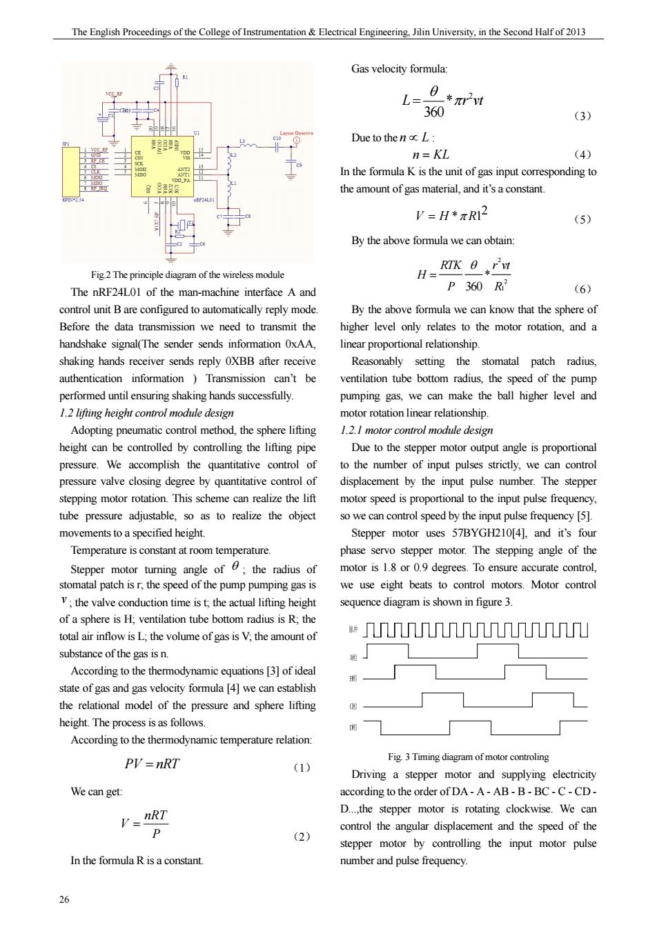
期 The English Proceedings of the College of Instrumentation & Electrical Engineering, Jilin University, in the Second Half of 2013 26 Fig.2 The principle diagram of the wireless module The nRF24L01 of the man-machine interface A and control unit B are configured to automatically reply mode. Before the data transmission we need to transmit the handshake signal(The sender sends information 0xAA, shaking hands receiver sends reply 0XBB after receive authentication information ) Transmission can’t be performed until ensuring shaking hands successfully. 1.2 lifting height control module design Adopting pneumatic control method, the sphere lifting height can be controlled by controlling the lifting pipe pressure. We accomplish the quantitative control of pressure valve closing degree by quantitative control of stepping motor rotation. This scheme can realize the lift tube pressure adjustable, so as to realize the object movements to a specified height. Temperature is constant at room temperature. Stepper motor turning angle of θ ; the radius of stomatal patch is r; the speed of the pump pumping gas is v ; the valve conduction time is t; the actual lifting height of a sphere is H; ventilation tube bottom radius is R; the total air inflow is L; the volume of gas is V; the amount of substance of the gas is n. According to the thermodynamic equations [3] of ideal state of gas and gas velocity formula [4] we can establish the relational model of the pressure and sphere lifting height. The process is as follows. According to the thermodynamic temperature relation: PV nRT = (1) We can get: nRT V P = (2) In the formula R is a constant. Gas velocity formula: 2 * 360 L r vt θ = π (3) Due to the n L ∝ : n KL = (4) In the formula K is the unit of gas input corresponding to the amount of gas material, and it’s a constant. 2 VH R = * 1 π (5) By the above formula we can obtain: 2 2 1 * 360 θ = RTK r vt H P R (6) By the above formula we can know that the sphere of higher level only relates to the motor rotation, and a linear proportional relationship. Reasonably setting the stomatal patch radius, ventilation tube bottom radius, the speed of the pump pumping gas, we can make the ball higher level and motor rotation linear relationship. 1.2.1 motor control module design Due to the stepper motor output angle is proportional to the number of input pulses strictly, we can control displacement by the input pulse number. The stepper motor speed is proportional to the input pulse frequency, so we can control speed by the input pulse frequency [5]. Stepper motor uses 57BYGH210[4], and it’s four phase servo stepper motor. The stepping angle of the motor is 1.8 or 0.9 degrees. To ensure accurate control, we use eight beats to control motors. Motor control sequence diagram is shown in figure 3. Fig. 3 Timing diagram of motor controling Driving a stepper motor and supplying electricity according to the order of DA - A - AB - B - BC - C - CD - D...,the stepper motor is rotating clockwise. We can control the angular displacement and the speed of the stepper motor by controlling the input motor pulse number and pulse frequency

Shi Zhaomin ete:The Research of Sphere Lifting Height Automatic Control System Based onAir Pressure Control 1.2.2 workable design so the result of the measurement is for temperature In order to make the valve open and close normally. compensation 8. We use spring and chute of a mechanical transmission mechanism.Setting the stomatal patch radius of 2 cm. 2 THE DESIGN OF SYSTEM SOFTWARE ventilation tube bottom radius of5cm,the workbench system mechanical diagram is shown in figure. GD 体状态 <到指今 状 发 Fig4 Mechanical figure of table system D示 Pressure control system of the workbench design has the following characteristics ontrol unit A The contrel uni (1)mechanical aspects:By connecting pneumatic valve diagram of the spring and c ting the other end th the fixed end,the alve is to provide guide Fig5 Flow chart of system softwar chute and avoid drawing phenomenon to appear the valve Control unit A displays receiving sphere movement because of the stepper motor rotation. state data and Scans buttons at every time.When the set (2)Controlling aspects:the reasonable design of the button is pressed we can set menu that sphere movement stomatal patch radius and ventilation tube base radius rising height rise time.such as man-machine interface make sphere lifting height and motor rottion ange send parameters to the control unit B through the linear relationship.We can control sphere lifting heigh wireless way. by motor more easily. After the control unit B receives the information from 13 height measurement module design the parameters of A.stepper motor open air valve System uses the ultrasonic ranging methods.The according to the instruction information.control valve method mainly emits tube gas volume by adjusting the rotation Angle of the the moment of timing th valveo the height of sphere.detect the spere same time.The ultrasonic wave in air immediately higher level at every time,and send higher level and encounter obstacles on the way back.the receiver receive rising time to the unit A through the wireless way. the reflected wave and immediately stop timing [61.The peed of the utrasonic propagation in the air is340 m/s 3 TEST DATA AND ANALYSIS to the timer recording time t,measure distances [as follows 3.System testing =340r/2 In order to verify the reliability of system and the (7 degree of adjusting precision.Room temperature is 25 Although it is in the lifting pipe height measurement degrees,atmospheric pressure is normal,rising time is3s because the lifting device ha od sealing system,lift ant value.We can test the system by setting heigh tube in different speed of the wind not affect the information random,and analyses of system error,Erro transmission of ultrasonic velocity and will not affect the distribution curve is shown in figure6 ultrasonic measurement precision.Temperature and humidity will affect the speed propagation. 27
Shi Zhaomin etc.: The Research of Sphere Lifting Height Automatic Control System Based on Air Pressure Control 27 1.2.2 worktable design In order to make the valve open and close normally, We use spring and chute of a mechanical transmission mechanism. Setting the stomatal patch radius of 2 cm, ventilation tube bottom radius of 5 cm, the workbench system mechanical diagram is shown in figure 4. Fig. 4 Mechanical figure of table system Pressure control system of the workbench design has the following characteristics: (1)mechanical aspects: By connecting pneumatic valve with one end of the spring and connecting the other end with the chute fixed end, the valve is to provide a guide chute and avoid drawing phenomenon to appear the valve because of the stepper motor rotation. (2)Controlling aspects: the reasonable design of the stomatal patch radius and ventilation tube base radius make sphere lifting height and motor rotation angle a linear relationship. We can control sphere lifting height by motor more easily. 1.3 height measurement module design System uses the ultrasonic ranging methods. The method mainly emits ultrasonic to a certain direction by ultrasonic emitter, in the moment of timing starts at the same time. The ultrasonic wave in air immediately encounter obstacles on the way back, the receiver receive the reflected wave and immediately stop timing [6]. The speed of the ultrasonic propagation in the air is 340 m/s . According to the timer recording time t, measure distances [7] as follows: s = 340 / 2 t (7) Although it is in the lifting pipe height measurement, because the lifting device has good sealing system, lift tube in different speed of the wind will not affect the transmission of ultrasonic velocity and will not affect the ultrasonic measurement precision. Temperature and humidity will affect the speed of ultrasonic propagation, so the result of the measurement is for temperature compensation [8]. 2THE DESIGN OF SYSTEM SOFTWARE Fig.5 Flow chart of system software Control unit A displays receiving sphere movement state data and Scans buttons at every time。When the set button is pressed ,we can set menu that sphere movement rising height, rise time, such as man-machine interface, and send parameters to the control unit B through the wireless way. After the control unit B receives the information from the parameters of A, stepper motor open air valve according to the instruction information, control valve tube gas volume by adjusting the rotation Angle of the valve ,control the height of sphere, detect the sphere’s higher level at every time, and send higher level and rising time to the unit A through the wireless way. 3TEST DATA AND ANALYSIS 3.1 System testing In order to verify the reliability of system and the degree of adjusting precision . Room temperature is 25 degrees, atmospheric pressure is normal, rising time is 3 s constant value. We can test the system by setting height information random, and analyses of system error , Error distribution curve is shown in figure 6
The English Proccedings of the College of Instrumentation&Electrical Engineeringin University,in the Second Halfof 2013 h=3315+0.607xAT)x 2 (12) Timing error range error caused by Ar 4h=340x4w (13) Total error is Ah=0.905×△T+170×M (14) System shows eror is.16cm,the relative emror of Fig6Eror distribution curve 145% 3.2 Analysis of the results The best local error analysis system actual height error The error analysis of the above test results is as is t.2cm,height error of 0.16cm.This system can follows: stably control sphere of lifting height.ensure the sphere to (1the actual higher level and set the height of the specify the height within the given time and. This error is relative to temperature error,pump gas 4、SUMMARY velocity and Angle error of the motor. Error is caused by the temperature error of AT How to arouse the enthusiasm of the students is an height important problem existing in the actual teaching the =12x298 △T×日 teachingto (8) students leaming efficiency,and active classroom atmosphere.System adopts motor closed-loop control The velocity error to the height of the error caused by method to precisely control the Angle of the machine. △y: we can control the sphere's height change precisely by the pipe ssure.The actual AH=OxAv within 0.2 cm .With temperature co 12×1000 (9 ultrasonic distance measurement method ,we can accurately indicates the lifting height of the ball.and Error is caused by motor Angleer of ensure that system actually displayed the emror is within 0.16 cm.the relative error is 1.45%.the system reflect the 过as of pipe pressure precisely and visually controlling the sphere movement Using the wireless (10) control,the teacher controls system conveniently and The actual eror is as follows: simply.Students can deeply understand the meaning of the air pressure.stimulate the thinking and explore the cientific knowledge. (11) References The actual error of system is.2cm,the relative error is 1.67% [1]Zhao Tong.Pneumatic Technology Development and The heighterror is as follows Application of the New Field [J].Shanghai:PTC The ranging error caused by the temperature error of technology BBS,2003. AT [2]Cui Bao-jian,Li Guo-xin.Precision pressure contro method based on proportional valve research 28
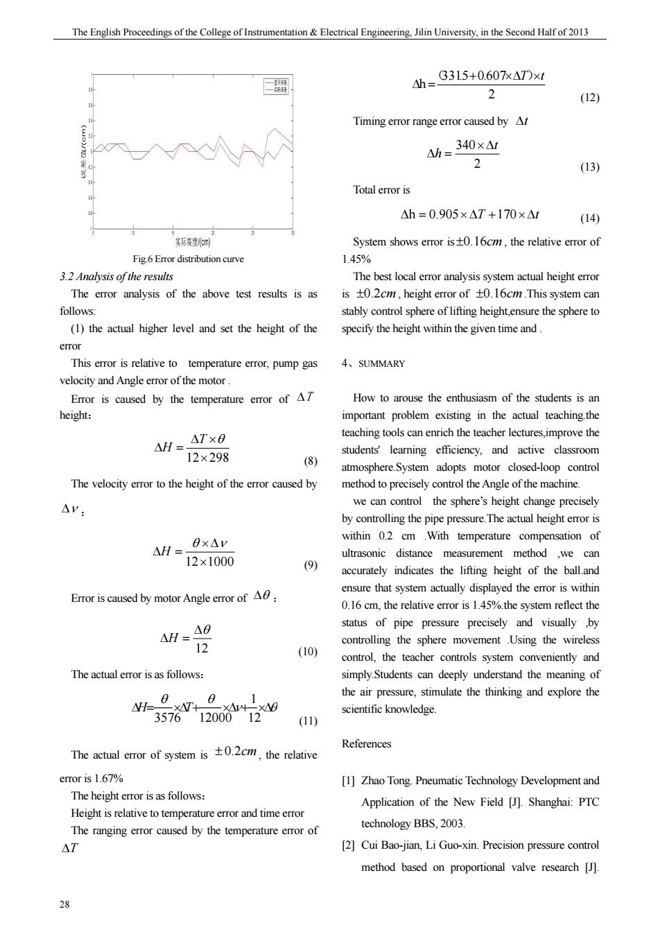
期 The English Proceedings of the College of Instrumentation & Electrical Engineering, Jilin University, in the Second Half of 2013 28 Fig.6 Error distribution curve 3.2 Analysis of the results The error analysis of the above test results is as follows: (1) the actual higher level and set the height of the error This error is relative to temperature error, pump gas velocity and Angle error of the motor . Error is caused by the temperature error of ΔT height: 12×298 Δ × Δ = T θ H (8) The velocity error to the height of the error caused by Δν : 12×1000 ×Δ Δ = θ ν H (9) Error is caused by motor Angle error of Δθ : 12 Δθ ΔH = (10) The actual error is as follows: ν θ θ θ Δ = ×Δ + ×Δ + ×Δ 12 1 3576 12000 H T (11) The actual error of system is ± 0.2cm, the relative error is 1.67% The height error is as follows: Height is relative to temperature error and time error The ranging error caused by the temperature error of ΔT 2 331.5 0.607 h + ×ΔT ×t Δ = ( ) (12) Timing error range error caused by Δt 2 340 t h ×Δ Δ = (13) Total error is Δh = 0.905×ΔT +170×Δt (14) System shows error is±0.16cm , the relative error of 1.45% The best local error analysis system actual height error is ±0.2cm , height error of ±0.16cm .This system can stably control sphere of lifting height,ensure the sphere to specify the height within the given time and . 4、SUMMARY How to arouse the enthusiasm of the students is an important problem existing in the actual teaching.the teaching tools can enrich the teacher lectures,improve the students' learning efficiency, and active classroom atmosphere.System adopts motor closed-loop control method to precisely control the Angle of the machine. we can control the sphere’s height change precisely by controlling the pipe pressure.The actual height error is within 0.2 cm .With temperature compensation of ultrasonic distance measurement method ,we can accurately indicates the lifting height of the ball.and ensure that system actually displayed the error is within 0.16 cm, the relative error is 1.45%.the system reflect the status of pipe pressure precisely and visually ,by controlling the sphere movement .Using the wireless control, the teacher controls system conveniently and simply.Students can deeply understand the meaning of the air pressure, stimulate the thinking and explore the scientific knowledge. References [1] Zhao Tong. Pneumatic Technology Development and Application of the New Field [J]. Shanghai: PTC technology BBS, 2003. [2] Cui Bao-jian, Li Guo-xin. Precision pressure control method based on proportional valve research [J]