
The English Proccedings of the College of Instrumentation&Electrical Engineeringin University,in the Second Halfof 2013 K1.2006. [Fisherpan.Show you know oscilloprobe[K]2010 [9]Zhongyi zhao.Principle of oscilloscope Maintenance and calibration[M].Beijing Electronie Industry Press.199:89-106 [10]Dongzhuo liu.Electronic measurement skills traininglK12005. [11]Shifu fan.Scientific instruments,live online application development trend.Modem Scientific Instruments [K2009 [12]Tianxudu,Bolin xie.phylogeny of instrument Journal of Chongqing University of Artsand Sciences28(4). [13]Shenlin wen.Physical experiment[M].Guangzhou South China university of technology press,1991. [14]Chengzhou ji.The basic knowledge of electronic oscillograph[J].physics,1975(06) [15]Wuhan University (electronic circuitTeaching Materials Writing Group.electronic circuit[M], Beijing:People's Education Press.1979 14
期 The English Proceedings of the College of Instrumentation & Electrical Engineering, Jilin University, in the Second Half of 2013 14 [K].2006. [8] Fisherpan.Show you know oscilloprobe[K].2010. [9] Zhongyi zhao.Principle of oscilloscope 、 Maintenance and calibration[M].Beijing : Electronic Industry Press,1990:89-106 [10]Dongzhuo liu.Electronic measurement skills training[K].2005. [11]Shifu fan.Scientific instruments, live online application development trend.Modern Scientific Instruments [K]2009. [12]Tianxudu,Bolin xie.phylogeny of instrument. Journal of Chongqing University of Artsand Sciences 28(4). [13]Shenlin wen.Physical experiment[M],Guangzhou: South China university of technology press,1991. [14]Chengzhou ji.The basic knowledge of electronic oscillograph[J],physics,1975(06). [15]Wuhan University《electronic circuit》Teaching Materials Writing Group.electronic circuit[M], Beijing:People's Education Press,1979
LiNa et Design and Implementationof the full range of sub-control inteligent lighting system Design and Implementation of the full range of sub-control intelligent lighting system LiNa:Zhang Tao:Ye Jiansong (College of Instrumentation and Electrical Engineering.Jilin UniversityChangchun 130021.China) Abstract-In order to create a good lighting environment,making full use of the outside natural light to control dynamic STCC5IRC single-chip mie the of ight LED LED drive circuits.It can automatically adjust the brightness supplemented by the outside light intensity,saving energy and realizing sub-regional contro functions.The detection accuracy of light intensity is less than 1.0 adjusting time is less than 2.0s,through actual measurement.Compared with ordinary fuorescent lamp,energy saving can rate up from25%to30% key ords-Liehtine system:Light inteusity sensor:Partition control:low power consumption:Energy saving incandescent lamp,half of a fluorescent.Compared 0 PREFACE with other lighting fixtures,LED lights contain no sodium,mercury and other elements which will do THE intelligence of traditional lighting systems is quite harm to people's health and thus can protect with lighting control,short environment to some degree2] longevity and low energy conversion efficiency besides,in some public places,such as classrooms,the 1 SYSTEM ARCHITECTURE use of light is often in unattended or poor management situation.which not only affects people's lives.but In this paper,the design of the full range of lighting also isa great waste of power.This paper mainly district ntelligent system is introducesa design of a modular lighting system able to monitor extemal light intensity in full directions by sensor module,drive circuit of LED module.LED each angle anytime and adjust its brightness module and arc lamp shade.The overall structure of automatically.This system uses the sub-regional the system is as shown in figure 1.The sensor module controlled manner.Each region can detect the light uses photosensitive diode to acquire extemnal light intensity outside and the intensity.And the detected signal is processed by control system processes the preamplifier,filter and AlD conversionthus there will information,then send signals to the controlling be digital signal.Through the IIC protocol the digital system,which will adjust the number of lights and signal will be transferred to the controlling system for then adjust the brightness so as to meet general processing.then through the LED drive circuit we can This lighting n no ontro the number of LED lights,inorder to meet the only meet the requirement of normal life and work general lighting requirements light intensity but the system can automatically adjus its brightness to facilitate the monitoring and management of public places. This system selects the LED as light source.LED is called the fourth generation of gre light source.Its emitting device is cold light source with low energy consumption,long longevity and other characteristics. In the case of the same lighting.the power 2 HARDWARE DESIGN consumption of LED lamp is one-tenth of an 15
Li Na etc.: Design and Implementation of the full range of sub-control intelligent lighting system 15 Design and Implementation of the full range of sub-control intelligent lighting system Li Na; Zhang Tao; Ye Jiansong (College of Instrumentation and Electrical Engineering, Jilin University ,Changchun 130021,China) Abstract—In order to create a good lighting environment, making full use of the outside natural light to control dynamic lights with low power consumption and intelligent characteristics, the intelligent lighting control system is based on the STC89C51RC single-chip microcontroller as the processor, composed of light intensity sensor module, LED module and LED drive circuits. It can automatically adjust the brightness supplemented by the outside light intensity, saving energy and realizing sub-regional control functions. The detection accuracy of light intensity is less than 1.0 lx, adjusting time is less than 2.0 s, through actual measurement. Compared with ordinary fluorescent lamp, energy saving can rate up from 25% to 30%. Key words—Lighting system; Light intensity sensor; Partition control; Low power consumption; Energy saving 0 PREFACE THE intelligence of traditional lighting systems is quite low, with uncontinuous lighting control, short longevity and low energy conversion efficiency; besides, in some public places, such as classrooms, the use of light is often in unattended or poor management situation, which not only affects people's lives, but also is a great waste of power. This paper mainly introduces a design of a modular lighting system able to monitor external light intensity in full directions by each angle anytime and adjust its brightness automatically. This system uses the sub-regional controlled manner. Each region can detect the light intensity outside automatically, and the microcontroller control system processes the information, then send signals to the controlling system, which will adjust the number of lights and then adjust the brightness so as to meet general lighting requirements[1]. This lighting system can not only meet the requirement of normal life and work light intensity ,but the system can automatically adjust its brightness to facilitate the monitoring and management of public places. This system selects the LED as light source. LED is called the fourth generation of green light source. Its emitting device is cold light source with low energy consumption, long longevity and other characteristics. In the case of the same lighting, the power consumption of LED lamp is one-tenth of an incandescent lamp, half of a fluorescent. Compared with other lighting fixtures, LED lights contain no sodium, mercury and other elements which will do harm to people’s health and thus can protect environment to some degree[2] 1 SYSTEM ARCHITECTURE In this paper, the design of the full range of lighting district intelligent system, is composed of STC89C51RC controller, BH1750FVI light intensity sensor module, drive circuit of LED module, LED module and arc lamp shade. The overall structure of the system is as shown in figure 1.The sensor module uses photosensitive diode to acquire external light intensity. And the detected signal is processed by preamplifier, filter and A\D conversion ,thus there will be digital signal. Through the IIC protocol the digital signal will be transferred to the controlling system for processing, then through the LED drive circuit we can control the number of LED lights, in order to meet the general lighting requirements. Fig.1 System architecture 2 HARDWARE DESIGN
The English Proceedings of the College of Instrumentation&Electrical Engineeringn University,in the Second Half of 2013 2.1 System Controlling Sructures Controlling systems are generally divided into the This design uses BH1750FVI,an integrated circuit closed loop control system and open-loop control for two-wire serial bus interface digital light intensity system.In this design,light intensity signal collected sensor.This integrated circuit can adjust the brightness requires feedback regulation so we choose closed loot of lights according to the collected light intensity data. ontro system[3].System structure is shown in Figun Taking advant wide range of light intensity[5].It has a spectral ⑧-网-a巴□ sensitivity of vision closed to human's eyes,which has a wide measuring range and high-precision(equals to 回 1lx-655351x)and other features Its inteal iruit/Dconverterand 2.2 The main controlling module signal transmission circuit.The diagram of the This system uses STC89C5IRC microcontroller as measurement circuit is shown in Figure 4.DI is the the controller.STC89C5IRC belongs to a class of 16 sensitive element of the module.through the buses with FLASH microcontroller.It uses a 16-bit pre-operational amplifier and filter,and then through a bus.peripherals and memory unified addressing 16-bitA/D converter the ouput signal is convertedto 4K,with the extema digital signal and finally through (IIC expanded memory available.With a unified interrupt signal is connected to the output terminal.The sensor management,it has a wealth of on-chip peripheral module contains an internal 3.3V power regulator modules.As for the FLASH-based,online debugging which can remove 50Hz/60Hz light noise ,then a and downloading is available.Because the JTAG port stable light intensity measurement can be achieved. and FET (FLASH EMULATION connected directly,no additional simulation tools are needed.it can work in low power modef4]'which is convenient and practical to use. The main controlling system circuit consists of ligh intensity sensor,LED driver modules,and powe Figure 3.Controllers are connected to measuring circuits with light intensity sensors in five directions namely,east,west,south,north and below.The array of LED lights in each partition is controlled individually Through extemal expansion,the LED driver circuits Fig 4 Measuring circuit schematics are connected to LED lights array in each partition. 2.4 LED driver module As is shown in Figure 5.port 1 is connected to the I port extended by LED driver module,using the switching characteristic of transistors to contro the LED lights.After testing the circuit,when there is a high level in the base,the output current is 1mA meeting the designed requirement.Resistor RI is 5K, avoiding output power shortage and playing a role in limiting current6]. Fig3 System hardware ciru 16
期 The English Proceedings of the College of Instrumentation & Electrical Engineering, Jilin University, in the Second Half of 2013 16 2.1 System Controlling Structures Controlling systems are generally divided into the closed loop control system and open-loop control system. In this design, light intensity signal collected requires feedback regulation so we choose closed loop control system[3]. System structure is shown in Figure 2. Fig.2 System Control Structures 2.2 The main controlling module This system uses STC89C51RC microcontroller as the controller. STC89C51RC belongs to a class of 16 buses with FLASH microcontroller. It uses a 16-bit bus, peripherals and memory unified addressing, whose addressing ranges up to 64K, with the external expanded memory available. With a unified interrupt management, it has a wealth of on-chip peripheral modules. As for the FLASH-based, online debugging and downloading is available. Because the JTAG port and FET (FLASH EMULATION TOOL) are connected directly, no additional simulation tools are needed .it can work in low power mode[4], which is convenient and practical to use. The main controlling system circuit consists of light intensity sensor, LED driver modules, and power supplies system. Hardware circuit diagram is shown in Figure 3.Controllers are connected to measuring circuits with light intensity sensors in five directions, namely, east, west, south, north and below. The array of LED lights in each partition is controlled individually by the fixed light intensity sensors. Through external expansion, the LED driver circuits are connected to LED lights array in each partition. Fig.3 System hardware circuit 2.3 Measuring circuit module This design uses BH1750FVI, an integrated circuit for two-wire serial bus interface digital light intensity sensor. This integrated circuit can adjust the brightness of lights according to the collected light intensity data. Taking advantage of its high resolution ,it can detect a wide range of light intensity[5]. It has a spectral sensitivity of vision closed to human’s eyes, which has a wide measuring range and high-precision (equals to 1lx-65535lx) and other features. Its internal circuit includes an A / D converter and a signal transmission circuit. The diagram of the measurement circuit is shown in Figure 4. D1 is the sensitive element of the module, through the pre-operational amplifier and filter, and then through a 16-bit A / D converter the output signal is converted to digital signal ,and finally through (IIC) protocol the signal is connected to the output terminal. The sensor module contains an internal 3.3V power regulator, which can remove 50Hz/60Hz light noise ,then a stable light intensity measurement can be achieved. Fig.4 Measuring circuit schematics 2.4 LED driver module As is shown in Figure 5, port 1 is connected to the I / O port extended by LED driver module, using the switching characteristic of transistors to control the LED lights. After testing the circuit, when there is a high level in the base, the output current is 1mA, meeting the designed requirement. Resistor R1 is 5K, avoiding output power shortage and playing a role in limiting current[6]
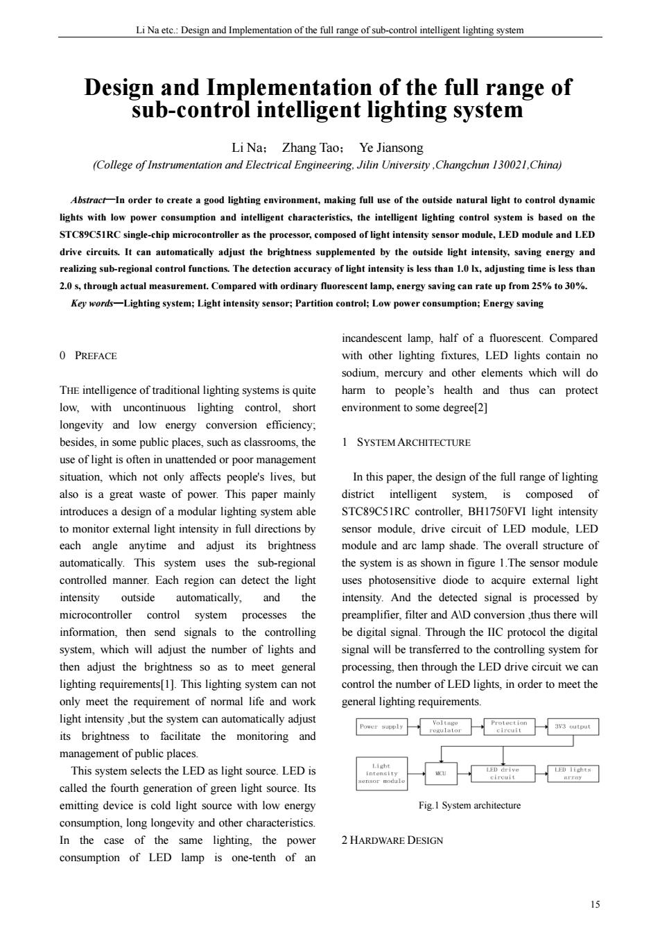
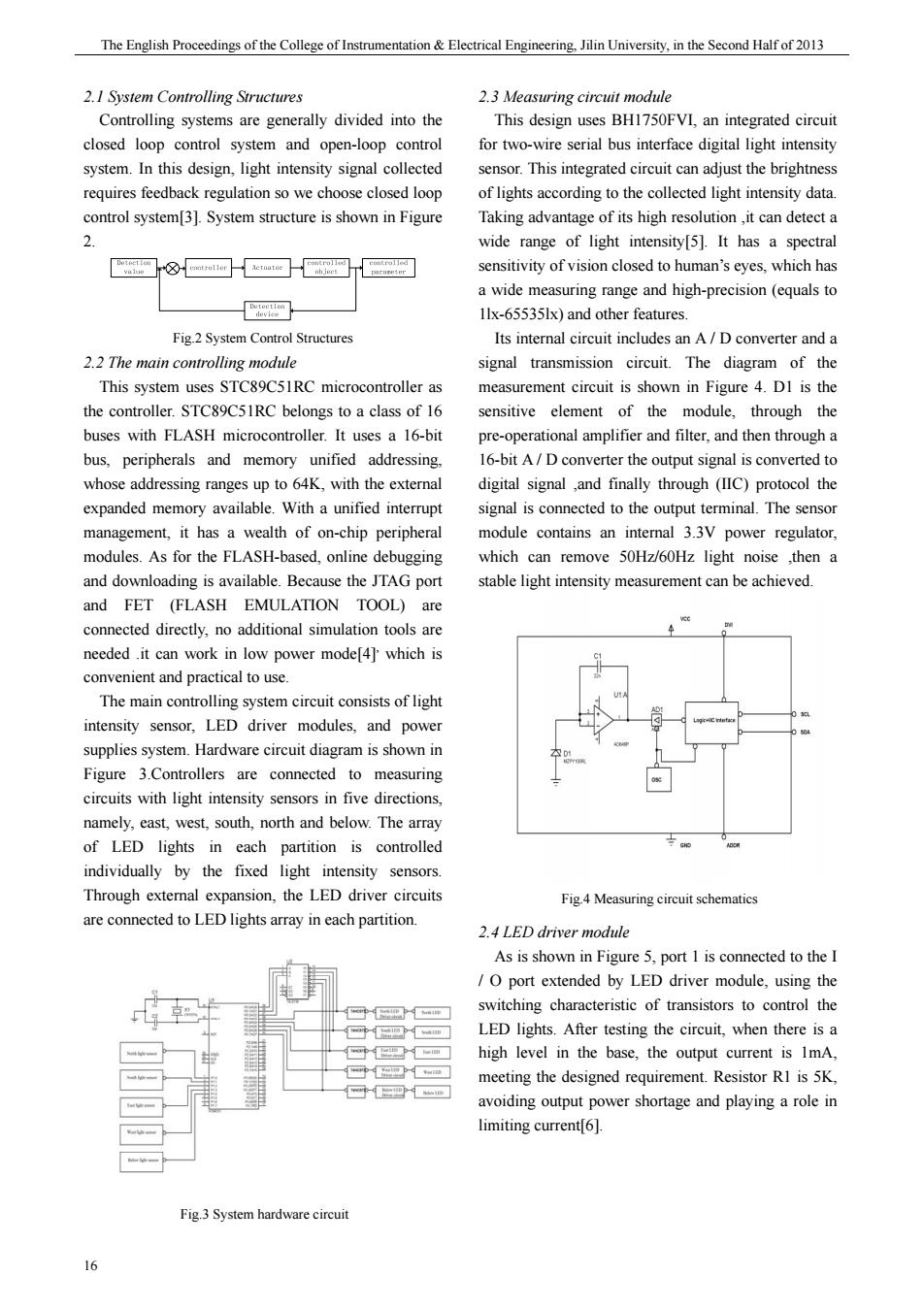
LiNa et:Design and Implementation of the full range of sub-conro intelligent lighting system the microprocessor will reduce the number of lights in the area,whereas will increase the number of lights in the area,as a result,the indoor light intensity will be maintained in the required range for general lighting requirements Fig5 LEDLamp driver circuit 2.5 LED lamp module According to the core concept of the design.that is reducing the waste of light to achieve the effect of environmental protection and saving money.therefore in this design,LED lights are arr nged in an arc.so that these lampscn provide light to the outside orl in full range of 360 degrees.LED lights above ard lamps are arrayed in five areas,namely,below,east. west,south,north.Figure 6 is the full range of Reduce lighns sub-control intelligent lighting system schematic. Figure7.Software system flow char 4 TEST RESULTS 。。 Test both the experimental prototype and the Fig.6 (a)Outline structure(Overlook ordinary lighting syste energy-s Under the same operating conditions,in the same 8888 environment of power consumption for 24 hours 8888 compared with ordinary lighting system,the intelligent lighting system saves about 25%-30%of the electricity.Detailed test results are shown in Fig.6 (b)Outline structure (Three-dimensional visual) 3 SOFTWARE DESIGN The main controller program flow chart is shown ir Figure 7.The program of the main controller include module initialization.gathering lighting information response processing and so on The main task is to the direction and ther obtain informatior from the direction of the light.if the in this direction exceeds ordinary lighting requirements. Fig.8 System energy saving effect test results 17
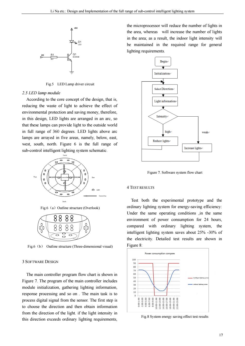
Li Na etc.: Design and Implementation of the full range of sub-control intelligent lighting system 17 Fig.5 LED Lamp driver circuit 2.5 LED lamp module According to the core concept of the design, that is, reducing the waste of light to achieve the effect of environmental protection and saving money, therefore, in this design, LED lights are arranged in an arc, so that these lamps can provide light to the outside world in full range of 360 degrees. LED lights above arc lamps are arrayed in five areas, namely, below, east, west, south, north. Figure 6 is the full range of sub-control intelligent lighting system schematic. Fig.6(a)Outline structure (Overlook) Fig.6(b) Outline structure (Three-dimensional visual) 3 SOFTWARE DESIGN The main controller program flow chart is shown in Figure 7. The program of the main controller includes module initialization, gathering lighting information, response processing and so on . The main task is to process digital signal from the sensor. The first step is to choose the direction and then obtain information from the direction of the light. if the light intensity in this direction exceeds ordinary lighting requirements, the microprocessor will reduce the number of lights in the area, whereas will increase the number of lights in the area; as a result, the indoor light intensity will be maintained in the required range for general lighting requirements. Figure 7. Software system flow chart 4 TEST RESULTS Test both the experimental prototype and the ordinary lighting system for energy-saving efficiency: Under the same operating conditions ,in the same environment of power consumption for 24 hours, compared with ordinary lighting system, the intelligent lighting system saves about 25% -30% of the electricity. Detailed test results are shown in Figure 8: Fig.8 System energy saving effect test results

The English Proccedings of the College of Instrumentation&Electrical Engineeringin University,in the Second Halfof 2013 system application.2012 S CONCLUSION [6]Kang Huaguang.Electronic Technology(Analog) This paper mainly introduces the full range of Higher education press06:116-118. intelligent lighting control system.Not only does the etection of ambient ligh intensity,but it also compensates for each other with the outside light intensity to adjust brightness automatically,which will meet the intelligent lighting requirements.Moreover.compared with the traditiona lighting system,the intelligent lighting system has five each of the LED lights array is equipped with a measuring circuit composed of light intensity sensors. five partitions are independent.realizing the purpose of sub-regional management.After actual test regional recognition rates up timei less than 2.0s,light intensity resolution is less tha 1.0lx.Compared with ordinary lighting system the intelligent lighting system saves about 25%30%of electricity in the same condition In addition the intelligent lighting system an achieve good en saving effect,extending lamp longevity.All th advantages guarantee the intelligent lighting control system a promising market prospect. References [1]Wang Wensheng.Intelligent lighting control and energy saving intelligent building and city information.2005. [2]Wang Xijuan LED intelligent lighting control system.Automation of manufacturing industry, 2012,33(12y128-131 [3]Wang Chunmin,Liu Xingming.Ji Yan Ju Continuous and discrete control system.Jilin University press..2008:4-6 [4]Yang Ping.Wang Wei.MSP430 series ultra low power microcontroller foreign electronic measurement technology.2008. [5]Yun zhonghua,Bai tianrui.indoor illumination intensity measuring instrument based on BH1750FVI [J].microcontroller and embedded 18
期 The English Proceedings of the College of Instrumentation & Electrical Engineering, Jilin University, in the Second Half of 2013 18 5 CONCLUSION This paper mainly introduces the full range of intelligent lighting control system. Not only does the system accomplish real-time detection of ambient light intensity, but it also compensates for each other with the outside light intensity to adjust brightness automatically, which will meet the intelligent lighting requirements. Moreover, compared with the traditional lighting system, the intelligent lighting system has five partitions ,they are east, west, south, north and below, each of the LED lights array is equipped with a measuring circuit composed of light intensity sensors, five partitions are independent, realizing the purpose of sub-regional management. After actual test, regional recognition rates up to 100%; settling time is less than 2.0s; light intensity resolution is less than 1.0lx. Compared with ordinary lighting system ,the intelligent lighting system saves about 25% -30% of electricity in the same condition. In addition, the intelligent lighting system can achieve good energy saving effect, extending lamp longevity. All the advantages guarantee the intelligent lighting control system a promising market prospect. References [1] Wang Wensheng. Intelligent lighting control and energy saving [J]. intelligent building and city information.2005. [2] Wang Xijuan LED intelligent lighting control system. Automation of manufacturing industry, 2012, 33 (12): 128-131. [3] Wang Chunmin, Liu Xingming, Ji Yan Ju. Continuous and discrete control system. Jilin University press,.2008:4-6. [4] Yang Ping, Wang Wei.MSP430 series ultra low power microcontroller [J]. foreign electronic measurement technology.2008. [5] Yun zhonghua, Bai tianrui. indoor illumination intensity measuring instrument based on BH1750FVI [J]. microcontroller and embedded system application.2012 [6] Kang Huaguang. Electronic Technology (Analog). Higher education press,.2006:116-118