CONTENTS Microcontroller-based mobile wireless charger design Ding Xiaoxu,Guo Baifu,Like 1 Pedestrian Dead Reckoning Device Design Based on STM32.. ...Luo Yin:Lu Hongzhou:Zhao Yu:Wang Jun 6 Transit Passenger Flow Statistics System design................ .....Xueyan hu;Lu bai;Xingzhi han 11 Design and Implementation of the full range of sub-control intelligent lighting system LiNa;Zhang Tao;Ye Jiansong 15 Research on wireless synchronization device in superficial seismic exploration. Zhang Lin-hang:Pei Li-ran;Sun Zi-chao;Wang Cong 19 The Research of Sphere Lifting Height Automatic Control System Based on Air Pressure Control Qian Chenghui:Shi Zhaomin;Kang Lili,LiQi 25 The design of lowcost Vibroseis based on FPGA.Qian Chenghuil;Shi Zhaomin;Li qi:Xu qian 30 Design of Gravitational Acceleration Measuring Device Based on Balance Method Qian Chenghui,Chen Changsong 36 A3D scanning and laser ranging device based on Triangulation CHEN Hao:HAN Xing-Zhi,TANG Xiang-Mei;JIANG Tao 42 The Design and Implementation about attendance system used in campus classroom based on RFID technology. Li Jiaoyang.WuZiyu;Piao Guanyu 48 Intelligent Multifunctional lamp.Zhang Zhuo;Chen jie-yuan;Zhang Wei 54 XYZ three-axis stepper motor control system... NieYang.LiTengFei,LiuHui 58 The dormitory intelligent security alarm system based on GSM wireless communication. .JiaoLei,ZhaoYue:WangZhengyu 62 A post-disaster Detection Rescue Robot System Design.. ...HU Rui-fan;WANG Hong-chao;PENG Yi-shuai 66 Development of early detection instrument for apnea syndromeXuLi-xi Wang Gang.Lian Shi-bo71 Design of nRF905-based Wireless Greenhouse for Environmental Parameters Detection and Transmission System. .....YangShuXin;LiuYang:LengShuZhe 77 Wireless multi-point temperature and humidity detection system design based on nRF4101 Wu Jindi;Song Qihan,Zhao Xiaoyi 81 The teaching auxiliary system based on the light cube. .......Xin Yi,Zhu Zhanshan;Chen Xu;Jiang Jian 85 Intelligent alarm system based on Yixuan;Zhou Xianze;Liu Yan 88 The calculation of mutual inductance of two polygons with arbitrarily position. .LiuYang.HeShengmin 92 Design and Realization of a Secondary Reclosing Microcomputer Device Remotely and Interactively Controlled
I CONTENTS Microcontroller-based mobile wireless charger design .........................................Ding Xiaoxu; Guo Baifu; Like 1 Pedestrian Dead Reckoning Device Design Based on STM32...................................................................................... ......................................................................................................... Luo Yin; Lu Hongzhou; Zhao Yu; Wang Jun 6 Transit Passenger Flow Statistics System design................................................ Xueyan hu; Lu bai; Xingzhi han 11 Design and Implementation of the full range of sub-control intelligent lighting system .............................................. .............................................................................................................................. Li Na; Zhang Tao; Ye Jiansong 15 Research on wireless synchronization device in superficial seismic exploration.......................................................... ......................................................................................... Zhang Lin-hang; Pei Li-ran; Sun Zi-chao; Wang Cong 19 The Research of Sphere Lifting Height Automatic Control System Based on Air Pressure Control ............................ .................................................................................................... Qian Chenghui; Shi Zhaomin; Kang Lili; Li Qi 25 The design of lowcost Vibroseis based on FPGA.........................Qian Chenghui1; Shi Zhaomin; Li qi; Xu qian 30 Design of Gravitational Acceleration Measuring Device Based on Balance Method ................................................... ..........................................................................................................................Qian Chenghui; Chen Changsong 36 A 3D scanning and laser ranging device based on Triangulation .................................................................................. ...............................................................................CHEN Hao; HAN Xing-Zhi; TANG Xiang-Mei; JIANG Tao 42 The Design and Implementation about attendance system used in campus classroom based on RFID technology...... ......................................................................................................................Li Jiaoyang; Wu Ziyu; Piao Guanyu 48 Intelligent Multifunctional lamp.............................................................Zhang Zhuo; Chen jie-yuan; Zhang Wei 54 XYZ three-axis stepper motor control system......................................................... NieYang; LiTengFei; LiuHui 58 The dormitory intelligent security alarm system based on GSM wireless communication........................................... ..........................................................................................................................JiaoLei; ZhaoYue; WangZhengyu 62 A post-disaster Detection Rescue Robot System Design............................................................................................... ................................................................................................. HU Rui-fan; WANG Hong-chao; PENG Yi-shuai 66 Development of early detection instrument for apnea syndrome ................. Xu Li-xia; Wang Gang; Lian Shi-bo 71 Design of nRF905-based Wireless Greenhouse for Environmental Parameters Detection and Transmission System . .....................................................................................................................YangShuXin; LiuYang; LengShuZhe 77 Wireless multi-point temperature and humidity detection system design based on nRF24L01 .................................... ...................................................................................................................... Wu Jindi; Song Qihan; Zhao Xiaoyi 81 The teaching auxiliary system based on the light cube.................................................................................................. ..........................................................................................................Xin Yi; Zhu Zhanshan; Chen Xu; Jiang Jian 85 Intelligent alarm system based on MMS ....................................................Zhang Yixuan; Zhou Xianze; Liu Yan 88 The calculation of mutual inductance of two polygons with multiturn coils at arbitrarily position .............................. ...........................................................................................................................................LiuYang; HeShengmin 92 Design and Realization of a Secondary Reclosing Microcomputer Device Remotely and Interactively Controlled
by PC ......Han Si-yu;Wang Yu;Ma Jing 97 The Design and Implementation of Electromagnetic Radiation Detector ..Wang Di:Ren Tian-ming:Jiang Ming-jie 105 The manufacture and simulation for electromagnetical damping of fiber detector.. ...Jiang Ransong:Zhou Rui;Xue Bixi109 ntelligent House Leakage Detection and Alarm System Li Suyi;Wang Duoqiang:Bai Yang:Zhang Weijie 121 Office computer displayer ofelectromagnetic radiation measure and alarm system.. .Yuan Guiyang:Shen Chunyang.Liu Gucheng 127 The Multi-frequency Signal Generating Technology for the Shallow Surface Detection ...Liu Chang-sheng:Kang Pan:Xia Zheng-vang:Zheng Wei 131 Fuzzy control based on ultrasonic ranging parking system model design.. QIAN Cheng-hui:FU yu-jing.MIAO Hong-song:KANG-ning 137
II by PC ......................................................................................................................Han Si-yu; Wang Yu; Ma Jing 97 The Design and Implementation of Electromagnetic Radiation Detector ..................................................................... ...............................................................................................................Wang Di; Ren Tian-ming; Jiang Ming-jie 105 The manufacture and simulation for electromagnetical damping of fiber detector ....................................................... ....................................................................................................................... Jiang Ransong; Zhou Rui; Xue Bixi 109 Intelligent House Leakage Detection and Alarm System .............................................................................................. .................................................................................................Li Suyi; Wang Duoqiang; Bai Yang; Zhang Weijie 121 Office computer displayer of electromagnetic radiation measure and alarm system..................................................... ....................................................................................................... Yuan Guiyang; Shen Chunyang; Liu Gucheng 127 The Multi-frequency Signal Generating Technology for the Shallow Surface Detection ............................................. ....................................................................................Liu Chang-sheng; Kang Pan; Xia Zheng-yang; Zheng Wei 131 Fuzzy control based on ultrasonic ranging parking system model design..................................................................... ............................................................................QIAN Cheng-hui; FU yu-jing; MIAO Hong-song; KANG-ning 137
Ding Xiaoxu et:Microcontroller-based mobile wireless charger design Microcontroller-based mobile wireless charger design Ding Xiaoxu,Guo Baifu;Like (Jilin Universiry of Instrument Science and Electrical Engineering.Changchun 130012) Abstracr-In order to adapt to the wireless charging of implantable medical devices,sensors,municipal transportation and ow-power principle of electromagnetic induction,through energy coupling coil,to achieve energy transfer,the current control,voltage contro achieve transmission distance 5cm.the voltage reaches 5V,0.5A current steady power supply,after the prompt is given full power and full automatically stop charging.Charging voltage and charging current display with low power LCD1602.System has a wireless charging,emergy transfer effect is good,low cost,no wiring,easy to carry and other dva s-STC12C5A60S2 MCU intelligent wireless charging distance can reach 5-10cm,voltage 5V,0.5A current FOREWORD stable charging.Has simple,wireless transmission PHONE needs the corresponding charger.most single chip microcomputer and LCD power chargers can not be universal and compatible portable consumption is more,lead to the problem of lower wired charger and charge the user is not easy.So a no charging current,so use low-power chips and liquid charger charging technology to be developed.Nokia crystal display,the charging current can be improved. 920 handset with a wireless charging technology I THE HARDWARE SYSTEM DESIGN receiving end have a coil,transmitter coil is connected wired power generating electromagnetic signals. The wireless charging system design using Receiver coil induction sending electromagnetic electromagnetic induction principle,the use of coil signals to generate current to the battery.But Nokia coupling to transfer energy.Due to the wireless 920 wireless charging.y you need to put the ssion of power voltage with energy sending corresponding wireless charging plate,on more thar unit and receiving unit coupling coil spacing D may 2 cm can not be charged,and the production process is change in the test.lead to different charging voltage complicated,expensive,visible increase the change of distance,design considerations for safety,so transmission distance is a wireless charging charging ways on the choice of constant voltage technology should pay attention to the issue.This scheme.On the device select select has design uses the same principle of electromagnetic variety of power saving mode.power consumptior induction to generate energy through the coil coupling province in particular,Strong anti-interference force of hardware circuits are transmitting and receiving ends MSP430 ultra-low power MCU series MSP430F2274 of two parts,transmitter using NE555 with the RC as monitoring of wireless transmission can charger oscillation circuit constituted,as a power amplifier control core chip,voltage and charging time display using FET devices;Receive omprised BUCK ith low power c onsumption LCD1602 LCD screer chopper circuit voltage type step-down DC/DC to improve the utilization efficiency of the energy of conversion circuit realized steady flow.Transmission the charging circuit
Ding Xiaoxu etc.: Microcontroller-based mobile wireless charger design 1 Microcontroller-based mobile wireless charger design Ding Xiaoxu; Guo Baifu; Like (Jilin University of Instrument Science and Electrical Engineering, Changchun 130012) Abstract—In order to adapt to the wireless charging of implantable medical devices, sensors, municipal transportation and other aspects of the application, Change the current electronic charging interface incompatibilities. The design uses a low-power microcontroller STC12C5A60S2 energy transfer charger as a wireless monitoring and control core,based on the principle of electromagnetic induction, through energy coupling coil, to achieve energy transfer, the current control, voltage control, achieve transmission distance 5cm, the voltage reaches 5V, 0.5A current steady power supply, after the prompt is given full power and full automatically stop charging。Charging voltage and charging current display with low power LCD1602.System has a wireless charging, energy transfer effect is good, low cost, no wiring, easy to carry and other advantages, has a broad application prospects. Keywords—STC12C5A60S2 MCU intelligent wireless charging FOREWORD PHONE needs the corresponding charger, most chargers can not be universal and compatible portable wired charger and charge the user is not easy. So a no charger charging technology to be developed. Nokia 920 handset with a wireless charging technology, using electromagnetic induction principle, sending and receiving end have a coil, transmitter coil is connected wired power generating electromagnetic signals, Receiver coil induction sending electromagnetic signals to generate current to the battery. But Nokia 920 wireless charging, you need to put the corresponding wireless charging plate, once more than 2 cm can not be charged, and the production process is complicated, expensive, visible increase the transmission distance is a wireless charging technology should pay attention to the issue. This design uses the same principle of electromagnetic induction to generate energy through the coil coupling, hardware circuits are transmitting and receiving ends of two parts, transmitter using NE555 with the RC oscillation circuit constituted, as a power amplifier using FET devices; Receive comprised BUCK chopper circuit voltage type step-down DC/DC conversion circuit realized steady flow. Transmission distance can reach 5-10cm, voltage 5V, 0.5A current stable charging. Has simple, wireless transmission distance is long, low-cost advantage. In the design of single chip microcomputer and LCD power consumption is more, lead to the problem of lower charging current, so use low-power chips and liquid crystal display, the charging current can be improved. 1 THE HARDWARE SYSTEM DESIGN The wireless charging system design using electromagnetic induction principle, the use of coil coupling to transfer energy. Due to the wireless transmission of power voltage with energy sending unit and receiving unit coupling coil spacing D may change in the test, lead to different charging voltage change of distance, design considerations for safety, so charging ways on the choice of constant voltage charging scheme. On the device select select has a variety of power saving mode, power consumption province in particular, Strong anti-interference force of MSP430 ultra-low power MCU series MSP430F2274 as monitoring of wireless transmission can charger control core chip, voltage and charging time display with low power consumption LCD1602 LCD screen, to improve the utilization efficiency of the energy of the charging circuit
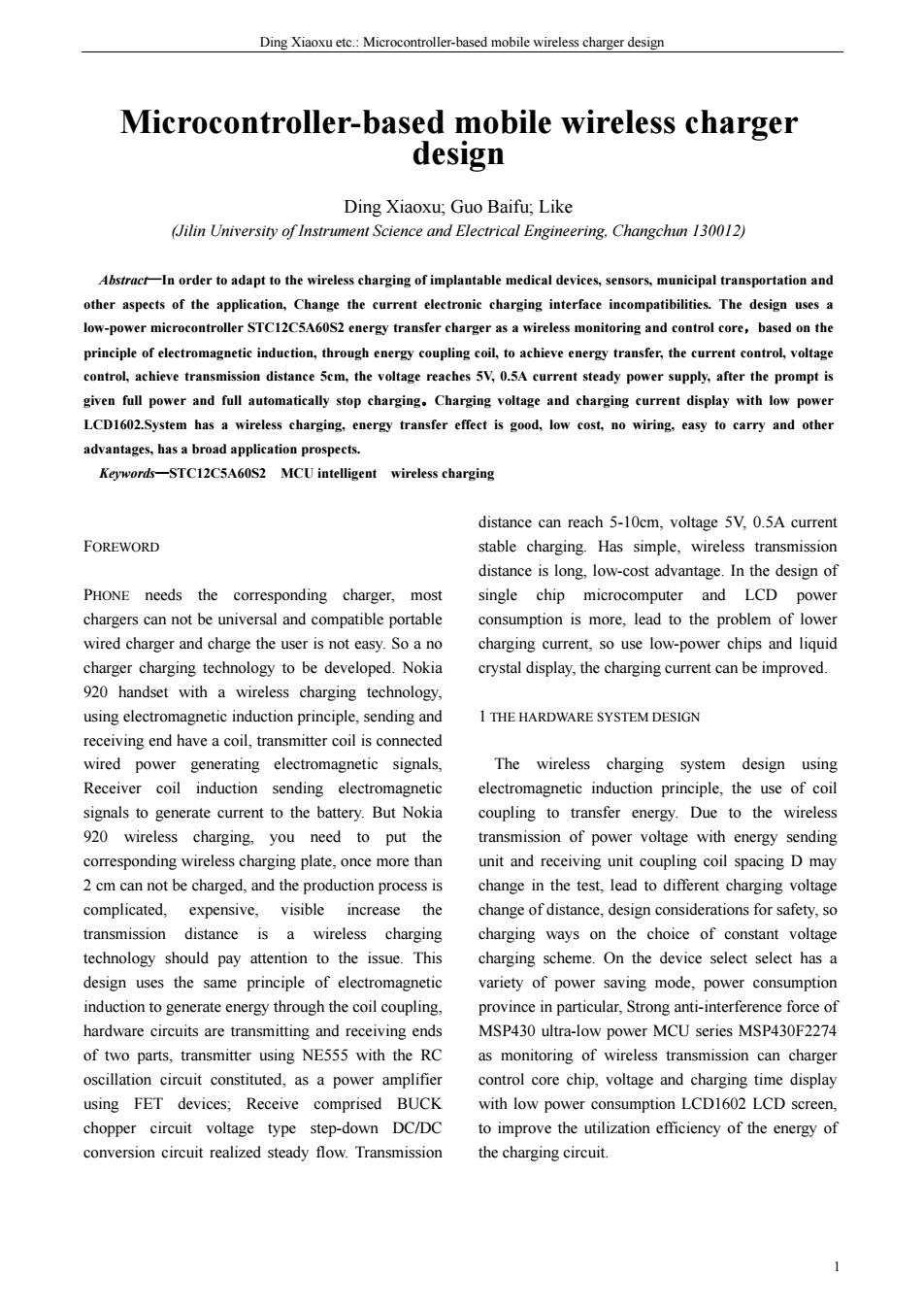
The English Proceedings of the College of Instrumen ation Electrical Engi eering.Jiin University,in the Second Halfof2013 Raltiecra Fig.I System architecture generating maximum altemating field consists of resonant achieve the best signal generator and a power amplifier,Shown in 1.2 Design of the half-bridge inverter circui Figure 2.Using NE555 constitute approximately Shown on the right in Figure 2 half-bridge inverter 55KHZ oscillation frequency of the signal generator, eireuit,half-bridge eircuit composed by two MOS which provides incentives for the signal amplifier switch.When the MOS transistor QI turns on,Q5 up circuit Resonant Power consists of LC current from the MOS transistor and go throug parallel resonant circuit and switch.Oscillation coil the LC circuit to ground.When the MOS transistor Q has a diameter of 0.50 mm enameled wire tightly is turned on,Q1 up,the current through Q2,LC to the wound 30 ring as required.Inductance value of about ground.So the cycle continues.direct current into 90 uH.Seen from the formula. alternating current by inverse.in order to transmit LC 1 circuit.Using IR2104 as the driver of MOS transistor f= chip.is a high voltage. When the resonance is at 55 KHZ,the capacitor value Q1 is turned on or off,which is controlled by the of C16 is about 0.luF.The resonant frequency of output of HO and LO control Q5 on and off,so as to control the half-bridge of the excitation signal in the e powe amplifiers.PA resonance,at this point the voltage and current in the coil reaches the maximum,thereby 2
期 The English Proceedings of the College of Instrumentation & Electrical Engineering, Jilin University, in the Second Half of 2013 2 Fig.1 System architecture 1.1 Oscillator circuit design Transmitter circuit consists of resonant oscillation signal generator and a power amplifier, Shown in Figure 2.Using NE555 constitute approximately 55KHZ oscillation frequency of the signal generator, which provides incentives for the signal amplifier circuit. Resonant Power Amplifier consists of LC parallel resonant circuit and switch. Oscillation coil has a diameter of 0.50 mm enameled wire tightly wound 3O ring as required. Inductance value of about 90 uH. Seen from the formula. 1 2 f π LC = When the resonance is at 55 KHZ, the capacitor value of C16 is about 0.1uF.The resonant frequency of frequency selection circuit is the same as the frequency of the excitation signal in the power amplifiers. PA resonance, at this point the voltage and current in the coil reaches the maximum, thereby generating maximum alternating electromagnetic field, achieve the best effect of energy transfer. 1.2 Design of the half-bridge inverter circuit Shown on the right in Figure 2 half-bridge inverter circuit, half-bridge circuit composed by two MOS switch. When the MOS transistor Q1 turns on, Q5 up, current from the MOS transistor Q1 and go through the LC circuit to ground. When the MOS transistor Q5 is turned on, Q1 up, the current through Q2, LC to the ground. So the cycle continues, direct current into alternating current by inverse, in order to transmit LC circuit. Using IR2104 as the driver of MOS transistor chip,IR2104 is a high voltage, high speed power MOSFET and IGBT driver, operating voltage 10-20V. Q1 is turned on or off ,which is controlled by the output of HO and LO control Q5 on and off, so as to control the half-bridge
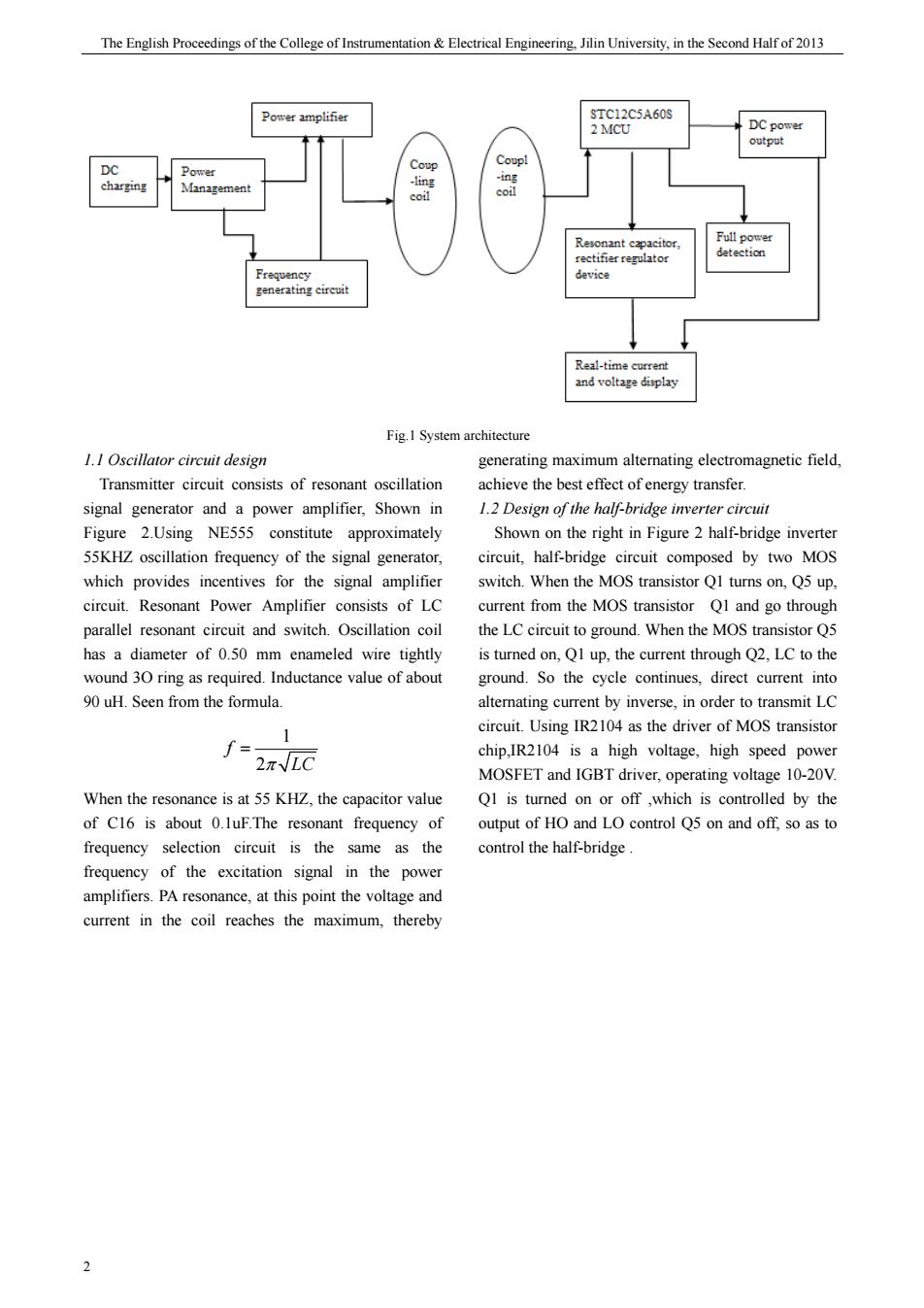
Ding Xiaoxu ete.:Microcontroller-based mobile wireless charger design 一RB360 R210 DI0 R38 N4148 Fig 2 The hardware circuit 1.3 BUCK chopper circui negative feedback of the DC/DC converter is fixed DC voltage into a the 15/16 feet of KA7500B.After power variable DC voltage,also called DC chopper.Buck microcontroller output PWM voltage,to KA7500B 15 circuit is a step-down chopper.The output average feet as the voltage reference.Output voltage through voltage Uo is less than the input voltage Ui.the same the voltage sampling resistor divider in the front compared with the voltage reference.when the voltage is too large.decrease the puse width when the voltae converter.BUCK converter also known as buck is too small,increase the pulse width,so that it converter,the series switching power supply, remains constant output voltage value.while the three-terminal switching buck regulator. output voltage set by key,ensure maximum output 1.3.I KA7500B Introduction and working principle voltage and current does not exceed the rated battery Circuit depicted in Figure3 is essentiallya powe supply circuit,with constant current/constant voltage output.It comes with two way feedback circuit that is output voltage to the following formula current feedback and voltage feedback.wherein the current feedback positive and negative corresponds to '=PwWM◆6.49k 10k the 1/2 feet of KA7500B.Outpu current pro voltage drop at the current sampling resistor The 2 PROCEDURAL FRAMEWORK FOR THE WHOLE SYSTEM pressure drop through resistor R9,R10 and R14,R15 feedback back.When KA7500B feetl voltage is The overall design work is mainly achieved by the greater than the first voltage feet2.KA7500B will microcontroller program control.which works as reduce the output pulse width (811 feet),the current follows:the ciruit startinitialization,the circuit is reduced,or increas tha the oupu funct seection output select and determine th current is constant at the default value,the curren output,the microcontroller calculates the output PWM value of the following formula: signal acquisition,regular data collection and 0.59K processing adjust the PWM signal duty,etc.,done by I=PWM* 0.59K+20/R adjusting the duty cycle voltage 2.1overall framework of the program shownin Figure Where R is the current sampling resistor,positive and 3
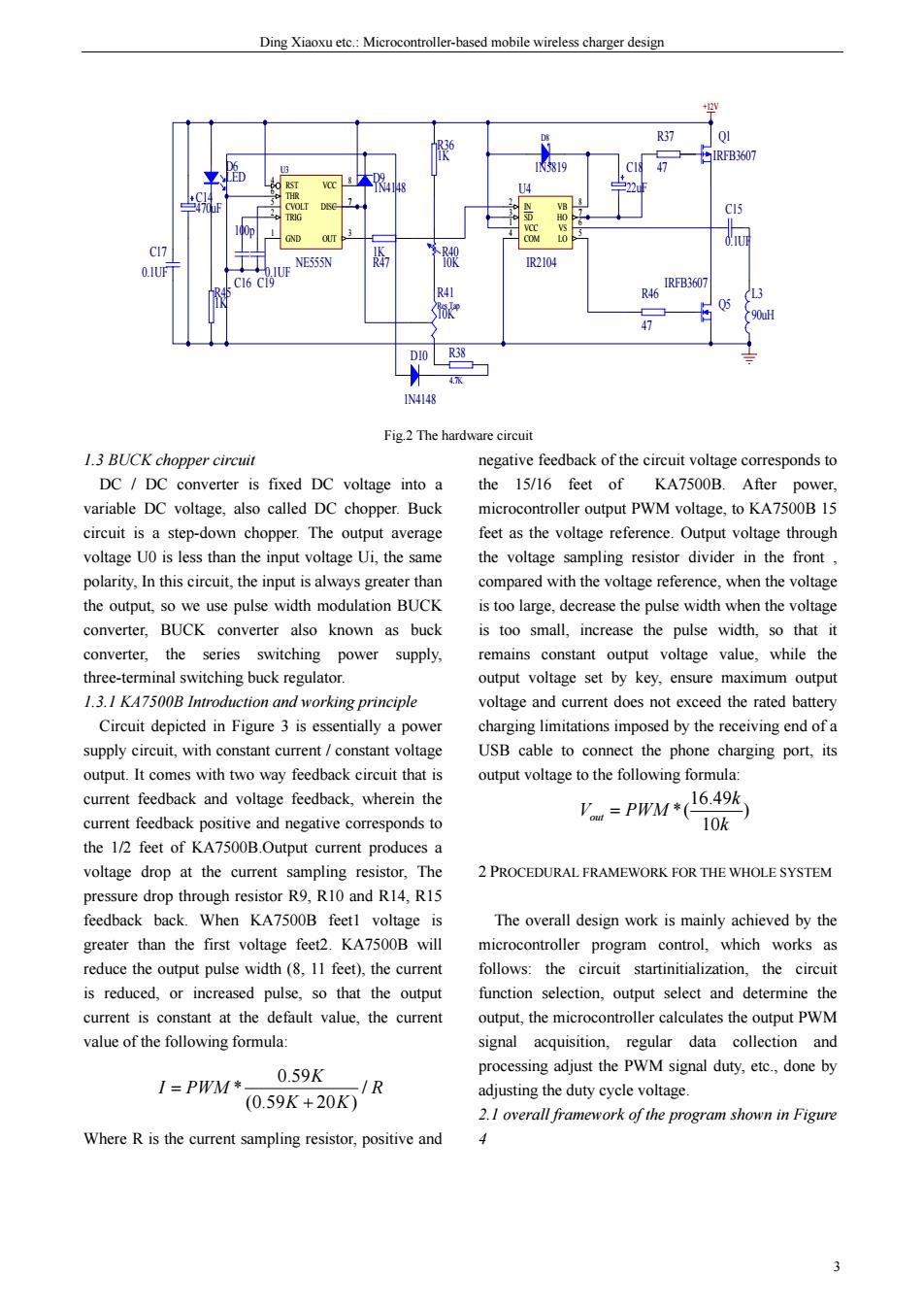
Ding Xiaoxu etc.: Microcontroller-based mobile wireless charger design 3 TRIG 2 OUT 3 RST 4 CVOLT 5 THR 6 DISC 7 VCC 8 GND 1 U3 NE555N +12V C19 0.1UF C16 100p R36 1K R47 1K R38 4.7K Q5 IRFB3607 Q1 IRFB3607 R37 47 R46 47 C15 0.1UF 90uH L3 C14 470uF R45 1K D6 LED R40 10K VCC 1 COM 4 VB 8 HO 7 VS 6 LO 5 IN 2 SD 3 U4 IR2104 D8 1N5819 C18 22uF C17 0.1UF 10K R41 Res Tap D9 1N4148 D10 1N4148 Fig.2 The hardware circuit 1.3 BUCK chopper circuit DC / DC converter is fixed DC voltage into a variable DC voltage, also called DC chopper. Buck circuit is a step-down chopper. The output average voltage U0 is less than the input voltage Ui, the same polarity, In this circuit, the input is always greater than the output, so we use pulse width modulation BUCK converter, BUCK converter also known as buck converter, the series switching power supply, three-terminal switching buck regulator. 1.3.1 KA7500B Introduction and working principle Circuit depicted in Figure 3 is essentially a power supply circuit, with constant current / constant voltage output. It comes with two way feedback circuit that is current feedback and voltage feedback, wherein the current feedback positive and negative corresponds to the 1/2 feet of KA7500B.Output current produces a voltage drop at the current sampling resistor, The pressure drop through resistor R9, R10 and R14, R15 feedback back. When KA7500B feet1 voltage is greater than the first voltage feet2. KA7500B will reduce the output pulse width (8, 11 feet), the current is reduced, or increased pulse, so that the output current is constant at the default value, the current value of the following formula: 0.59 * / (0.59 20 ) K I PWM R K K = + Where R is the current sampling resistor, positive and negative feedback of the circuit voltage corresponds to the 15/16 feet of KA7500B. After power, microcontroller output PWM voltage, to KA7500B 15 feet as the voltage reference. Output voltage through the voltage sampling resistor divider in the front , compared with the voltage reference, when the voltage is too large, decrease the pulse width when the voltage is too small, increase the pulse width, so that it remains constant output voltage value, while the output voltage set by key, ensure maximum output voltage and current does not exceed the rated battery charging limitations imposed by the receiving end of a USB cable to connect the phone charging port, its output voltage to the following formula: 16.49 *( ) 10 out k V PWM k = 2 PROCEDURAL FRAMEWORK FOR THE WHOLE SYSTEM The overall design work is mainly achieved by the microcontroller program control, which works as follows: the circuit startinitialization, the circuit function selection, output select and determine the output, the microcontroller calculates the output PWM signal acquisition, regular data collection and processing adjust the PWM signal duty, etc., done by adjusting the duty cycle voltage. 2.1 overall framework of the program shown in Figure 4