Luo Yin etc:Pedestrian Dead Reckoning Device Design BasednSTM32 projected onto the xy plane after tilt compensation7] ssind as Hx Hy,the heading angle Aof pedestrian can be expressed by formula(4): 男=%+cosA H=M sin+M sin (1) 3.2 Heading angle calculation H,=M,sin 0,sin 0,+M,cos 0-M.sin 0;cos The pitch(represented by0l and the tilt angle (represented by02)of the sensor module calculated by the Ax,Ay,Az measured by the three-dimensional (4) The Mx、My、Mz is the three-axis magnetic field component after ellipsoid correction8. 3.3 Count of the number of step and stride estimate Since the three-dimensional sensor module is placed on the waist of pedestrian the accelerometer can a=acal丁E+E A detec e of pedestrian,the vertical acceleration n threshold The Ax,Ay,Az in the formula(2)is acquired by the determination method is used to count the number of triaxial acceleration values corrected through least step.Meanwhile,the stride frequency(Hz)and stride squares method [61 Since the sensor module is placed length(m)of pedestrian has linear relationship and can on the waist of pedestrian.It is inevitably introduce be used the following mode]toestimate: ibration isturbance when the pedestrian is walking. 0.4375. ≤1.35 and result in pitch and tilt angle solving error,a S- 0.45F-0.17,135<F<2.45 complementary filtering algorithm is used to integrate 0.9325 2.45≤f<ao (5) with the data produced by the gyroscope to reduce Where S is the real-time stride length of pedestrian interference of solving error caused by vibration let F is pedestrian's real time walking frequency.To count e the three-axis data of the gyro scope after the real time walking frequeney in thedat performing filtering complementary algorithm as Gx terminal can determine the real time stride lengthof Gy,Gz.and three direction acceleration data afte pedestrian,and reduce the travel distance statistical fusion as Ax',Ay'.Az'The weight of three directions error. acceleration as PAx、PAy、PAz.the weight of hrce-axis gyroscope data as PGx、PGy、PGz,thc 4TEST RESULT AND ANALYSIS A=(A,×P+G,×P)MP旺+P) Field test result is shown in Figure6,the test site is the school internal standard athletic field.the athletic A.=(A.xP:+G,xP)/(P:+P) field included two straight lane,one is set form the west to the east,and the other is set from the east to A=(A×P+G,xP)P+P) the west The fifth is chosen nd the (3) lane walking length is 430m.the actual number of steps is By reducing the weight of the acceleration values 560.The number of steps measured by dead reckoning and improving the weight of three-axis data of is 587,the measured walking distance is 428.5m.The relative statistical error of the number of step is 4 8% ula(3)we car ror of walking di stance is less than I%.Compared with the actual route.the combine with three-axis magnetic field components maximum deviation is 5m,appears in the straight lane Mx、My、Mz measured by the electronic which is set from the east to the west,the deviation compass,suppose the component of the magnetic field interval length is 85m.the heading angle measured
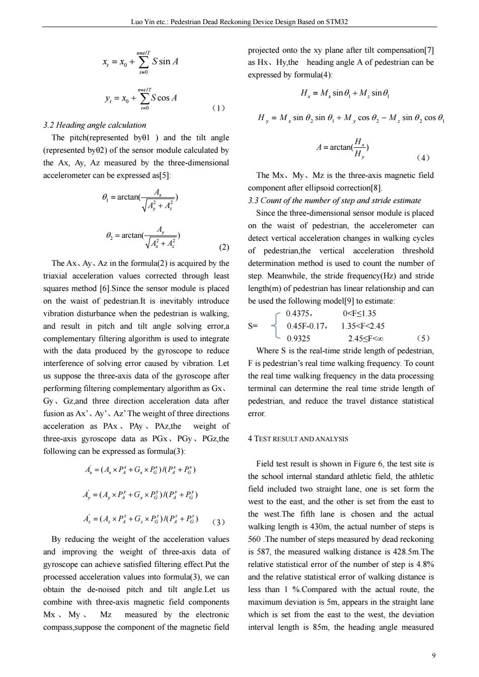
Luo Yin etc.: Pedestrian Dead Reckoning Device Design Based on STM32 9 / 0 0 sin n tT t i x x SA = = = + ∑ ∑ = = = + n t T i yt x S A / 0 0 cos (1) 3.2 Heading angle calculation The pitch(represented byθ1 ) and the tilt angle (represented byθ2) of the sensor module calculated by the Ax, Ay, Az measured by the three-dimensional accelerometer can be expressed as[5]: arctan( ) 2 2 1 y z x A A A + θ = arctan( ) 2 2 2 x z y A A A + θ = (2) The Ax、Ay、Az in the formula(2) is acquired by the triaxial acceleration values corrected through least squares method [6].Since the sensor module is placed on the waist of pedestrian.It is inevitably introduce vibration disturbance when the pedestrian is walking, and result in pitch and tilt angle solving error,a complementary filtering algorithm is used to integrate with the data produced by the gyroscope to reduce interference of solving error caused by vibration. Let us suppose the three-axis data of the gyroscope after performing filtering complementary algorithm as Gx、 Gy、Gz,and three direction acceleration data after fusion as Ax’、Ay’、Az’ The weight of three directions acceleration as PAx 、 PAy 、 PAz,the weight of three-axis gyroscope data as PGx、PGy、PGz,the following can be expressed as formula(3): ( )/( ) ' x G x A x x G x Ax = Ax × PA + G × P P + P ( )/( ) ' y G y A y y G y Ay = Ay × PA + G × P P + P ( )/( ) ' z G z A z z G z Az = Az × PA + G × P P + P (3) By reducing the weight of the acceleration values and improving the weight of three-axis data of gyroscope can achieve satisfied filtering effect.Put the processed acceleration values into formula(3), we can obtain the de-noised pitch and tilt angle.Let us combine with three-axis magnetic field components Mx 、 My 、 Mz measured by the electronic compass,suppose the component of the magnetic field projected onto the xy plane after tilt compensation[7] as Hx、Hy,the heading angle A of pedestrian can be expressed by formula(4): 1 1 Hx = M x sinθ + M z sinθ 2 1 2 2 1 H y = M x sin θ sin θ + M y cos θ − M z sin θ cos θ arctan( ) y x H H A = (4) The Mx、My、Mz is the three-axis magnetic field component after ellipsoid correction[8]. 3.3 Count of the number of step and stride estimate Since the three-dimensional sensor module is placed on the waist of pedestrian, the accelerometer can detect vertical acceleration changes in walking cycles of pedestrian,the vertical acceleration threshold determination method is used to count the number of step. Meanwhile, the stride frequency(Hz) and stride length(m) of pedestrian has linear relationship and can be used the following model[9] to estimate: 0.4375, 0<F≤1.35 S= 0.45F-0.17, 1.35<F<2.45 0.9325 2.45≤F<∞ (5) Where S is the real-time stride length of pedestrian, F is pedestrian’s real time walking frequency. To count the real time walking frequency in the data processing terminal can determine the real time stride length of pedestrian, and reduce the travel distance statistical error. 4 TEST RESULT AND ANALYSIS Field test result is shown in Figure 6, the test site is the school internal standard athletic field, the athletic field included two straight lane, one is set form the west to the east, and the other is set from the east to the west.The fifth lane is chosen and the actual walking length is 430m, the actual number of steps is 560 .The number of steps measured by dead reckoning is 587, the measured walking distance is 428.5m.The relative statistical error of the number of step is 4.8% and the relative statistical error of walking distance is less than 1 %.Compared with the actual route, the maximum deviation is 5m, appears in the straight lane which is set from the east to the west, the deviation interval length is 85m, the heading angle measured
The English Proceedings of the College of Instrumentation&Electrical Engineering.n University,in the Second Halfof 013 error isor less.It is indicated that the above [3]Sun Zuolei.Mao Xuchu Zhang Xiangfen.Tian method designed walker dead reckoning device has a Weifeng.The pedestrian positioning parameter high accuracy,timeliness and reliability and meets the needs of practical application. correction based on particle filtering and probabilistic neural network[].The Joumnal of 50 Shanghai Jiaotong University,200906:885-889 [4]Song Min,Shen Yanchun,Indoor Positioning dead reckoning algorithm and implementation[J] Computer Engineering.2013,07:294 [5]ST Corporation AN3182 Application Note[OL] http:www.st.com/intemet/com//TECHNICALLIT ERATURE/DATASHEET/Doc ID 17289:13 [6]ST Corporation AN3182 Application Note[OL]. Figure the test result schematic http:www.st.com/intemet/com/TECHNICALRES OUCES/TECHNICALLITERATURE/DATASHE 5EPILOGUE ET/Doe ID 17353:24 The article describes the hardware and software [7]ST Corporation AN3182 Application Note[OL] algorithms design of the pedestrian dead reckoning http:www.st.com/intemet/com/TECHNICALRES device the OUCES/TECHNICALLITERATUREDATASHE ET/Doc ID 17353:7 data acquisition and dead reckoning.The system which uses micro inertial devices and the [8]Chen Weitao.Zhang Yun.Electronic compass micro-controller can meet the applicable requirement design based on LSM303DLHC[OL] the ease of setting up a system Field experimen http://www.paper.edu.cn/releasepaper/content/201 prove that the measurement accuracy can meet the 301-948:1-8 actual demand. [9]Sun Zuolei,Mao Xuchu,Zhang Xiangfen,Tian Weifeng.Pedestrian dead reckoning based on References motion recognition and stride estimation [The [1]Lei Fang.Panos J.Antsaklis,Montestruque,Brett Joural of Shanghai Jiaotong University,2008, MeMickell.Design of a Wireless Assisted 122004 Pedestrian Dead Reckoning System-The NavMote Experience[J].IEEE TRANSACTIONS ON INSTRUMENTATION AND MEASUREMENT,2005,12.2342-2355 [2]Lauro Ojeda,Johann Borenstein,Non-GPS Navigation with the Personal Dead-Reckoning System[R].SPIE Defense and Security Conference, Unmanned Systems Technology IX,Orlando Florida,April 9-13.2007 10
期 The English Proceedings of the College of Instrumentation & Electrical Engineering, Jilin University, in the Second Half of 2013 10 error is ±2。~±4。or less. It is indicated that the above method designed walker dead reckoning device has a high accuracy, timeliness and reliability and meets the needs of practical application. Figure 6 the test result schematic 5 EPILOGUE The article describes the hardware and software algorithms design of the pedestrian dead reckoning device based on the micro-controller STM32F103RBT6, which completes the multi-sensor data acquisition and dead reckoning. The system which uses micro inertial devices and the micro-controller can meet the applicable requirement of miniaturization, practicality and portability and has the ease of setting up a system.Field experiments prove that the measurement accuracy can meet the actual demand. References [1] Lei Fang,Panos J. Antsaklis,Montestruque,Brett McMickell,Design of a Wireless Assisted Pedestrian Dead Reckoning System—The NavMote Experience[J].IEEE TRANSACTIONS ON INSTRUMENTATION AND MEASUREMENT, 2005,12:2342-2355. [2] Lauro Ojeda,Johann Borenstein, Non-GPS Navigation with the Personal Dead-Reckoning System[R].SPIE Defense and Security Conference, Unmanned Systems Technology IX, Orlando, Florida, April 9-13, 2007 [3] Sun Zuolei,Mao Xuchu,Zhang Xiangfen,Tian Weifeng,The pedestrian positioning parameter correction based on particle filtering and probabilistic neural network[J].The Journal of Shanghai Jiaotong University,2009,06:885-889 [4] Song Min,Shen Yanchun,Indoor Positioning dead reckoning algorithm and implementation[J]. Computer Engineering,2013,07:294 [5] ST Corporation AN3182 Application Note[OL]. http:www.st.com/internet/com//TECHNICALLIT ERATURE/DATASHEET/Doc ID 17289:13 [6] ST Corporation AN3182 Application Note[OL]. http:www.st.com/internet/com/TECHNICALRES OUCES/TECHNICALLITERATURE/DATASHE ET/Doc ID 17353:24 [7] ST Corporation AN3182 Application Note[OL]. http:www.st.com/internet/com/TECHNICALRES OUCES/TECHNICALLITERATURE/DATASHE ET/Doc ID 17353:7 [8] Chen Weitao,Zhang Yun,Electronic compass design based on LSM303DLHC[OL]. http://www.paper.edu.cn/releasepaper/content/201 301-948:1-8 [9] Sun Zuolei,Mao Xuchu,Zhang Xiangfen,Tian Weifeng,Pedestrian dead reckoning based on motion recognition and stride estimation [J].The Journal of Shanghai Jiaotong University, 2008, 12:2004
Xueyan hu etc:Transit Passenger Flow Statistics System design Transit Passenger Flow Statistics System design Xueyan hu Lu bai Xingzhi han Abstract-Recently,the urban traffic iams in serious condition,bus as one of the most common means of transport is on the other hand,it's nearly empty in times of trafic low.Moreover,faced with the situation buses dispatching at regula r time,some people choose to buy their own cars,what made traffic in a wors adition.Considering resolving this problem,we designed a transit passenger flow statistics system,which would make a reasonable provision of public transport resources,and then contribute to alleviating the pressure on traffic.Transit passenge now statistics system consist of transmitting part and receiving part.Transmitting part using Infrared Emitting Diode and Photodiode calculators the pas nger flow on the bus,then acquired the current location and speed through GPS.and sent ,te.the bu stops a ad Tr it Co Dispatch Center)by wireless.The who was waiting at the site could observe operating conditions through the LCD of the bus stops,in order that th passengers would make the most rational choice,saving time to facilitate travel.Transit Company Dispatch Center would schedule bus trips according to passenger flow conditions,in that way could help conserve resources and satisfy transport needs Keywords-bus:GPS:MSP430:people- ounting consist of radiating portion and receiving portion. 0 INTRODUCTION Radiating portion is used in the bus to achieve people counting to get the current speed and location THE present situation of the urban traffic is not by GPS,and send the information to the receiving optimistic.especially the peak commuting in my portion,receiving portion shows the message by LCD opinion,in order to solve this situation,there are two to allow the passenger to choose the best way,the ways to go.on the one hand,improving the situation of overall block diagram show as Figure 1. road and enhancing road construction,on the othe hand enhancing the management of road and People counting GPS improving use of existing resources.though the government is going on the first way,but there are a lot of works to do,relatively speaking the second way can 430 controller remit current situation quickly and effectively,so this passage do a research about the second wav current will improve the current situation bviously.as th same time,we can achieve the energy conservation anc 430 controller emission reduction intelligent transportation system is the only way which is passed in the future.if there are LCD module enough loose and comfortable bus,i think people will car,in order toi Figure overall block diagram transportation system,people counting and scheduling is very important. 2ACHIEVEMENTAND ARRANGEMENT OF PARTS ITHE OVERALL DESIGN OF THE PROJECT 2.I radiating circuit module Radia ing circuit module includes MSP430F169 Transit Passenger Flow Statistics System PCB.GPS module,radiating circuit and double red
Xueyan hu etc.: Transit Passenger Flow Statistics System design 11 Transit Passenger Flow Statistics System design Xueyan hu Lu bai Xingzhi han Abstract—Recently,the urban traffic jams in serious condition,bus as one of the most common means of transport is overcrowded in the rush hour,on the other hand,it's nearly empty in times of traffic low.Moreover,faced with the situation of buses dispatching at regular time , some people choose to buy their own cars,what made traffic in a worse condition.Considering resolving this problem ,we designed a transit passenger flow statistics system, which would make a reasonable provision of public transport resources, and then contribute to alleviating the pressure on traffic.Transit passenger flow statistics system consist of transmitting part and receiving part.Transmitting part using Infrared Emitting Diode and Photodiode calculators the passenger flow on the bus ,then acquired the current location and speed through GPS, and sent these information to receiving part (i.e. the bus stops and Transit Company Dispatch Center) by wireless. The passengers who was waiting at the site could observe operating conditions through the LCD of the bus stops ,in order that the passengers would make the most rational choice, saving time to facilitate travel.Transit Company Dispatch Center would schedule bus trips according to passenger flow conditions ,in that way could help conserve resources and satisfy transport needs. Keywords—bus;GPS;MSP430;people-counting; wireless communication 0 INTRODUCTION THE present situation of the urban traffic is not optimistic,especially the peak commuting,in my opinion,in order to solve this situation,there are two ways to go,on the one hand,improving the situation of road and enhancing road construction,on the other hand,enhancing the management of road and improving use of existing resources.though the government is going on the first way,but there are a lot of works to do,relatively speaking,the second way can remit current situation quickly and effectively,so this passage do a research about the second way.current bus is a great resource,if we can use it effectively,it will improve the current situation obviously,as the same time,we can achieve the energy conservation and emission reduction,intelligent transportation system is the only way which is passed in the future.if there are enough loose and comfortable bus, i think people will choose bus but not private car, in order to intelligent transportation system, people counting and scheduling is very important. 1THE OVERALL DESIGN OF THE PROJECT Transit Passenger Flow Statistics System is consist of radiating portion and receiving portion. Radiating portion is used in the bus to achieve people counting,to get the current speed and location by GPS,and send the information to the receiving portion, receiving portion shows the message by LCD to allow the passenger to choose the best way,the overall block diagram show as Figure 1. Figure 1.the overall block diagram 2 ACHIEVEMENT AND ARRANGEMENT OF PARTS 2.1 radiating circuit module: Radiating circuit module includes MSP430F169 PCB,GPS module,radiating circuit and double red
The English Proceedings of the College of Instrumentation Electrical Engineering.Jilin University,in the Second Half of 2013 outside to the tubePS module and wireless modul gear into MSP430 by serial port,radiating circuit begin module show as figure 2. Serial port init Send finished?N wait Send data Send GPS data Figure of radiating module 2.2 receiving portion Figure chart portior Receiving module includes MS430F149 3.1.I people counting module PCB.wireless module LCD circuit.LCD is controlled people counting module consist of red outside to by parallel port,wireless module connect to serial the tube it's output voltage is high when people ort,module circuit show as figure 3. pass on the contrary it's output voltage is low flow chart of people counting module show as figure5. begin Serial port init ens Number++ Figure 3.circuit of receiving module sensor output low? 3 SOFTWARE DESIGN umber-一 Software includes receiving portion and radiating portion 3.I radiating portion Tasks of radiating portion are people counting GPS send data flow chart of end Map,speed measur hart of people ounting n 3.1.2 GPS module The key of using of GPS module is to formulate the communication protocol of Serial port,it includes 12
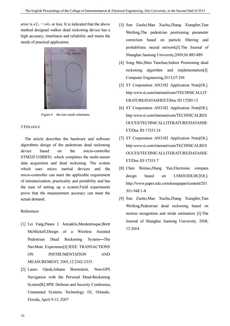
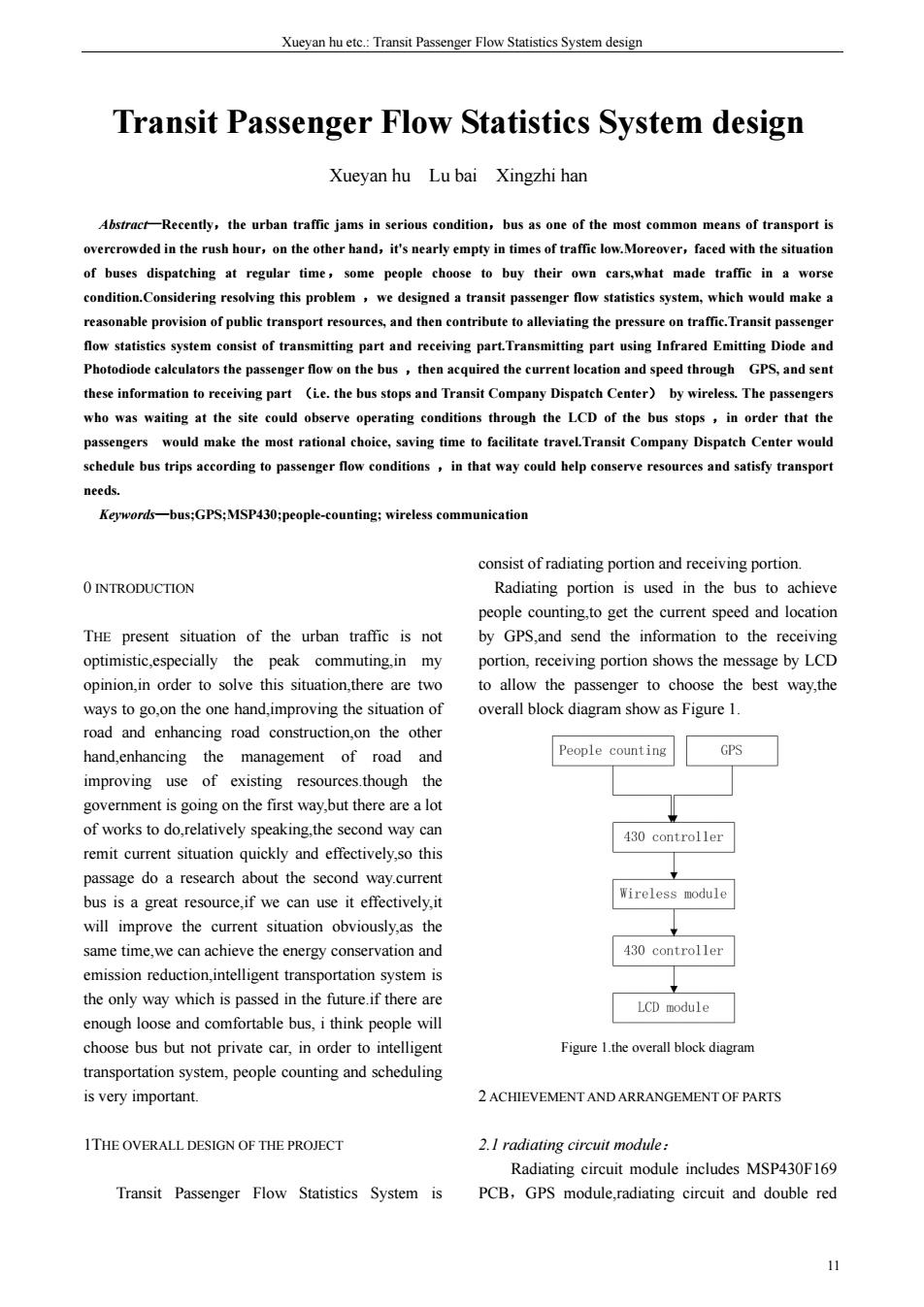
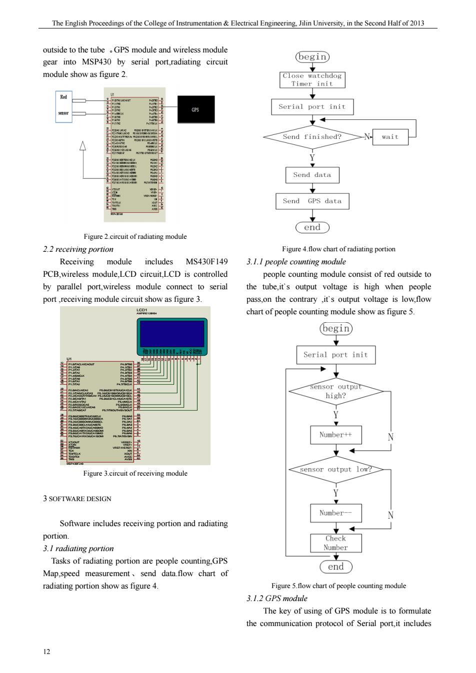
期 The English Proceedings of the College of Instrumentation & Electrical Engineering, Jilin University, in the Second Half of 2013 12 outside to the tube 。GPS module and wireless module gear into MSP430 by serial port,radiating circuit module show as figure 2. Figure 2.circuit of radiating module 2.2 receiving portion Receiving module includes MS430F149 PCB,wireless module,LCD circuit,LCD is controlled by parallel port,wireless module connect to serial port ,receiving module circuit show as figure 3. P2.5/ROSC/CA5 25 P2.4/CA1/TA2 24 P2.3/CA0/TA1 23 P2.2/CAOUT/TA0/CA4 22 P2.1/TAINCLK/CA3 21 P2.0/ACLK/CA2 20 P1.2/TA1 14 P1.1/TA0 13 P1.0/TACLK/CAOUT 12 P1.3/TA2 15 P1.4/SMCLK 16 P1.7/TA2 19 P1.6/TA1 18 P1.5/TA0 17 P2.6/ADC12CLK/CA6 26 P2.7/TA0/CA7 27 P3.0/UCB0STE/UCA0CLK 28 P3.1/UCB0SIMO/UCB0SDA 29 P3.2/UCB0SOMI/UCB0SCL 30 P3.3/UCB0CLK/UCA0STE 31 P3.4/UCA0TXD/UCA0SIMO 32 P3.5/UCA0RXD/UCA0SOMI 33 P3.6/UCA1TXD/UCA1SIMO 34 P3.7/UCA1RXD/UCA1SOMI 35 P4.5/TB5 41 P4.4/TB4 40 P4.3/TB3 39 P4.2/TB2 38 P4.1/TB1 37 P4.0/TB0 36 P4.6/TB6 42 P4.7/TBCLK 43 AVCC 64 AVSS 62 P5.0/UCB1STE/UCA1CLK 44 P5.1/UCB1SIMO/UCB1SDA 45 P5.2/UCB1SOMI/UCB1SCL 46 P5.3/UCB1CLK/UCA1STE 47 P5.4/MCLK 48 P5.5/SMCLK 49 P5.6/ACLK 50 P5.7/TBOUTH/SVSOUT 51 P6.0/A0 59 P6.1/A1 60 P6.2/A2 61 P6.3/A3 2 P6.4/A4 3 P6.5/A5 4 P6.6/A6 5 P6.7/A7/SVSIN 6 XT2OUT 52 XT2IN 53 RST/NMI 58 TCK 57 TDI/TCLK 55 TMS 56 VEREF+ 10 VREF+ 7 XIN 8 XOUT 9 TDO/TDI 54 VREF-/VEREF- 11 U1 MSP430F249 CS1 1 CS2 2 GND 3 VCC 4 V0 5 RS 6 R/W 7 E 8 DB0 9 DB1 10 DB2 11 DB3 12 DB4 13 DB5 14 DB6 15 DB7 16 RST 17 -Vout 18 LCD1 AMPIRE128X64 Figure 3.circuit of receiving module 3 SOFTWARE DESIGN Software includes receiving portion and radiating portion. 3.1 radiating portion Tasks of radiating portion are people counting,GPS Map,speed measurement、send data.flow chart of radiating portion show as figure 4. Figure 4.flow chart of radiating portion 3.1.1 people counting module people counting module consist of red outside to the tube,it`s output voltage is high when people pass,on the contrary ,it`s output voltage is low,flow chart of people counting module show as figure 5. Figure 5.flow chart of people counting module 3.1.2 GPS module The key of using of GPS module is to formulate the communication protocol of Serial port,it includes

Xueyan hu etc.:Transit Passenger Flow Statistics System design data type and information format data type contains Testing on the outdoor,data can be showed mainly Binary information and NMEA information accurately on the LCD.result of testing show as table these two types of information can correspond with 1 GPS by serial port,flow chart of GPS module show as Test Number of people longitude latitude speed (kmh) figure6 the car 33 12535 6 12535438825 17 12535458838 5 CONCLUSION Finally,Transit Passenger Flow Statistics System is finished.it n chieve display ofum r.speed.and position,according to the control mode designed,the goal which passengers choose bus based on the Read bour message is attained. As the same time.dispatching center realizes the effective dispatching.depending on the message A Bibliography [1]Xu sun.Electronic oscilloscope development in Figure 6.flow chart of GPS module the challenge[J].Foreign Electronic Measurement The main task of receivin portion is showing the Technology 2009(03). number of people and position [2]Lin zhang.12-BitData-Acquisition System information meanwhile,to response the IRQ of MAX197 and Its Application in the Harm on ic receiving data.flow chart of receiving portion show as Analyzer [J]electronics engineer,2002,(5). figure7. 3]Bing yin,Huiqing wang,Zhi yang.Lattice LCD hegin display module MGLS??12864TInterface and programming [J]Joumal of henan university, 2000,(5). [4]MAXIM Company product information collection [M]2002. [5]Zhitian wang Radio electronics measurement [M]volume one.Beijing:Atomic Energy Press, 2002:243-312 [6]Tek company .TDS3000 A series of digital Figure 7.flow chart Fluorescent oscilloscope user manual[K]2004. 4 SYSTEM TESTING [7]Yinghang zhou.The principle and types of probes 13
Xueyan hu etc.: Transit Passenger Flow Statistics System design 13 data type and information format data type contains mainly Binary information and NMEA information, these two types of information can correspond with GPS by serial port, flow chart of GPS module show as figure 6. Figure 6.flow chart of GPS module 3.2 receiving portion The main task of receiving portion is showing the number of people and position information ,meanwhile,to response the IRQ of receiving data, flow chart of receiving portion show as figure 7. Figure 7.flow chart of receiving portion 4 SYSTEM TESTING Testing on the outdoor,data can be showed accurately on the LCD,result of testing show as table 1. Table 1.result of testing 5 CONCLUSION Finally,Transit Passenger Flow Statistics System is finished,it can achieve display of number,speed,and position,according to the control mode designed ,the goal which passengers choose bus based on the message is attained. As the same time , dispatching center realizes the effective dispatching,depending on the message. Bibliography [1] Xu sun.Electronic oscilloscope development in the challenge[J]. Foreign Electronic Measurement Technology,2009(03). [2] Lin zhang. 12-BitData-Acquisition System MAX197 and Its Application in the Harm on ic Analyzer[J].electronics engineer,2002,(5). [3] Bing yin,Huiqing wang,Zhi yang. Lattice LCD display module MGLS??12864TInterface and programming [J].Journal of henan university, 2000,(5). [4] MAXIM Company product information collection [M].2002. [5] Zhitian wang.Radio electronics measurement [M] .volume one.Beijing:Atomic Energy Press, 2002:243-312 [6] Tek company .TDS3000 A series of digital Fluorescent oscilloscope user manual[K].2004. [7] Yinghang zhou.The principle and types of probes