ELECTRIC CIRCUIT reference direction of voltage and current are inversed,we should insert a""in the right of Eq.(1-7. 人 u FIGURE1-9The symbol ofinductor The energy of inductor is (1-8) Thus energy is stored by the inductor in a magnetic field.As the current is increased,so too is the stored magnetic energy.Note,however that this energy is zero whenever the current is zero.Because the energy associated with the inductance parameter increases and decreases with the current,we can properly conclude that the inductor has the property of being capable of returning energy to the source from which it receives it.The average power of inductor is zero. Example 1-2 The current through a 0.IH inductor is )=10/e4.Find the voltage across the inductor and the energy stored in it Solution Since u=Ldildt ,and L=0.1H,u=Ldil dt=e-s'(1-51)/ The energy stored initis 1-6 THE CAPACITANCE PARAMETER Attention is next directed to capacitance,the third basic parameter of electric circuit theory In a general way capacitance can be characterized as that property of a circuit lement in which energy is capable of being stored in a electric field.A significant and distinguishing feature of capacitance is that its influence in an electric circuit is manifested only when there is a changing voltage between the terminals of the circuit element. Capacitance is the proportionalitl factor relating the charge between two metal surfaces or conductors)to the corresponding voltage existing between them.Then we have Q=Cu (1-9) Where q represents the charge and u denotes the voltage,and C represents the capacitance parameter Lowercase letters are used here to stress the instantaneous nature of the quantities. Because the relation of the current and the charge is i=dq/dt (1-10)
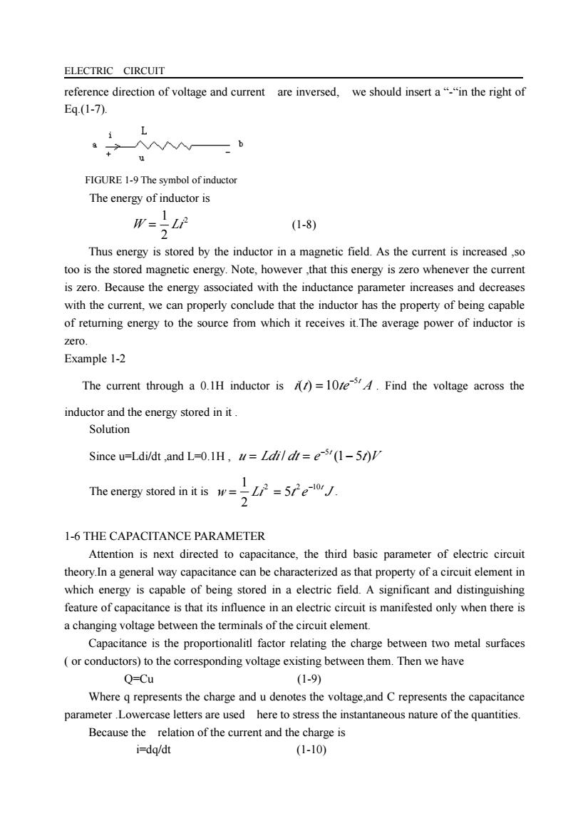
ELECTRIC CIRCUIT reference direction of voltage and current are inversed, we should insert a “-“in the right of Eq.(1-7). FIGURE 1-9 The symbol of inductor The energy of inductor is 2 2 1 W = Li (1-8) Thus energy is stored by the inductor in a magnetic field. As the current is increased ,so too is the stored magnetic energy. Note, however ,that this energy is zero whenever the current is zero. Because the energy associated with the inductance parameter increases and decreases with the current, we can properly conclude that the inductor has the property of being capable of returning energy to the source from which it receives it.The average power of inductor is zero. Example 1-2 The current through a 0.1H inductor is i t te A5t ( ) 10 − = . Find the voltage across the inductor and the energy stored in it . Solution Since u=Ldi/dt ,and L=0.1H , u Ldi dt e t V t / (1 5 ) 5 = = − − The energy stored in it is w Li t e J 2 2 10t 5 2 1 − = = . 1-6 THE CAPACITANCE PARAMETER Attention is next directed to capacitance, the third basic parameter of electric circuit theory.In a general way capacitance can be characterized as that property of a circuit element in which energy is capable of being stored in a electric field. A significant and distinguishing feature of capacitance is that its influence in an electric circuit is manifested only when there is a changing voltage between the terminals of the circuit element. Capacitance is the proportionalitl factor relating the charge between two metal surfaces ( or conductors) to the corresponding voltage existing between them. Then we have Q=Cu (1-9) Where q represents the charge and u denotes the voltage,and C represents the capacitance parameter .Lowercase letters are used here to stress the instantaneous nature of the quantities. Because the relation of the current and the charge is i=dq/dt (1-10)
ELECTRIC CIRCUIT By substituting Eq.(1-9)into Eq.(1-10),we can obtain i=C(du/dt) (1-11) This expression shows the manner in which the current flowing through a capacitance parameter is related to the voltage appearing across it.Any circuit element showing the property of yielding a current which is directly proportional to the rate of change of the voltage between its terminals is called a capacitor,and its unit is F(Farad).A capacitor usually consists of large metal surfaces separated by small distances.The symbol of capacitor is shown as Fig.1-11. +u FIGURE 1-11The symbol of capacitor The reference direction of voltage and current in equation (1-11)are same and if the reference direction of voltage and current are inversed,we should insert a"in the right of Eq.(1-11) The energy of inductor is W-TOi (1-12) Equation (1-12)states that the capacitor absorbs an amount of energy which is proportional to the capacitance parameter and the square of the instantaneous value of the voltage appearing across the capacitor.The absorbed energy in turn is stored by the capacitor in an electric field existing between its two plates.Note that as the capacitor voltage increases. the energy increases,and as the capacitor voltage decreases in magnitude,the associated energy decreases.Again,it is reasonable to conclude therefore that like the conductor,the capacitor has the capacitl of interchanging energy with the source.This stands in sharp contrast with the resistor,which can only disspate energy in the form of heat.The average power of inductor is zero. 1-7 IDEAL INDEPENDENT CURRENT AND VOLTAGE SOURCES All electric circuits are drived by sources.These sources may be independent of other network variables.as in the case of synchronous generators that are used to supply energy to homes and many industrial and commercial loads;or they may be of a dependent type,such as those that are frequently encountered in electronic circuits.Attention here is confined to the independent type.However,independence of a circuit variable such as current or voltage does not imply independence of time.Accordingly,many independent sources are often time-varying,as with the synchronous generator whose phase voltage is described by )=Esin/,where is determined by the speed of rotation of the generator
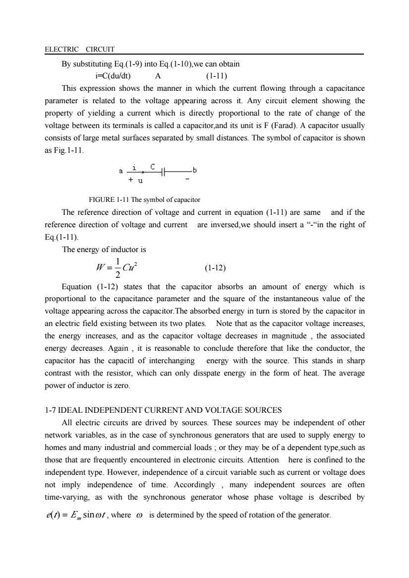
ELECTRIC CIRCUIT By substituting Eq.(1-9) into Eq.(1-10),we can obtain i=C(du/dt) A (1-11) This expression shows the manner in which the current flowing through a capacitance parameter is related to the voltage appearing across it. Any circuit element showing the property of yielding a current which is directly proportional to the rate of change of the voltage between its terminals is called a capacitor,and its unit is F (Farad). A capacitor usually consists of large metal surfaces separated by small distances. The symbol of capacitor is shown as Fig.1-11. FIGURE 1-11 The symbol of capacitor The reference direction of voltage and current in equation (1-11) are same and if the reference direction of voltage and current are inversed,we should insert a “-“in the right of Eq.(1-11). The energy of inductor is 2 2 1 W = Cu (1-12) Equation (1-12) states that the capacitor absorbs an amount of energy which is proportional to the capacitance parameter and the square of the instantaneous value of the voltage appearing across the capacitor.The absorbed energy in turn is stored by the capacitor in an electric field existing between its two plates. Note that as the capacitor voltage increases, the energy increases, and as the capacitor voltage decreases in magnitude , the associated energy decreases. Again , it is reasonable to conclude therefore that like the conductor, the capacitor has the capacitl of interchanging energy with the source. This stands in sharp contrast with the resistor, which can only disspate energy in the form of heat. The average power of inductor is zero. 1-7 IDEAL INDEPENDENT CURRENT AND VOLTAGE SOURCES All electric circuits are drived by sources. These sources may be independent of other network variables, as in the case of synchronous generators that are used to supply energy to homes and many industrial and commercial loads ; or they may be of a dependent type,such as those that are frequently encountered in electronic circuits. Attention here is confined to the independent type. However, independence of a circuit variable such as current or voltage does not imply independence of time. Accordingly , many independent sources are often time-varying, as with the synchronous generator whose phase voltage is described by e t E t ( ) = m sinω , where ω is determined by the speed of rotation of the generator
ELECTRIC CIRCUIT Independent voltage source The distinguishing feature of an independent voltage source is that the value of the voltage is not dependent on either the magnitude or the direction of the current flowing through the source.Figure 1-12(a)depicts the model representation of such a two-terminal source.The lowercase letter is used when the character or value of the source is unspecified or time-varying Tf the voltage source is known to be an ideal battery,then the uppercase symbol Us is used to denote its value,as illustrated in Fig.1-12(b).Displayed in Fig 1-12(c)is the voltage-current characteristic of an ideal constant-voltage source.Observe that the characteristic is parallel to the current(horizontal)axis,which is entirely consistent with the fact that any value of current magnitude and direction can be associated with the voltage source.Of course,it is assumed that the voltage source is not being operated beyond its energy capability;otherwise,the ideal representation would no longer be valid. Us 0 Current,i (a) (b) ( FIGURE1-12 The independent voltage source.(a)Symbolic representation;(b)specific example of a battery as a voltage source(c)the u-icharacteristic. A notable point about an ideal voltage source is its zero internal resistance Independent current source The ideal independent current source is a two-terminal element which supplies its specified current to the circuit in which it is placed independently of the value and direction of the voltage appearing between its terminals.Displayed in Fig 1-13(a)is the symbol used to represent the current source,while Fig.1-13(b)shows the u-i characteristic.The internal resistance of an ideal current source is infinite. 01tage, Current,i (a) (b) FIGURE1-13The indepe (a) tion,(b)the u-icharacteristic
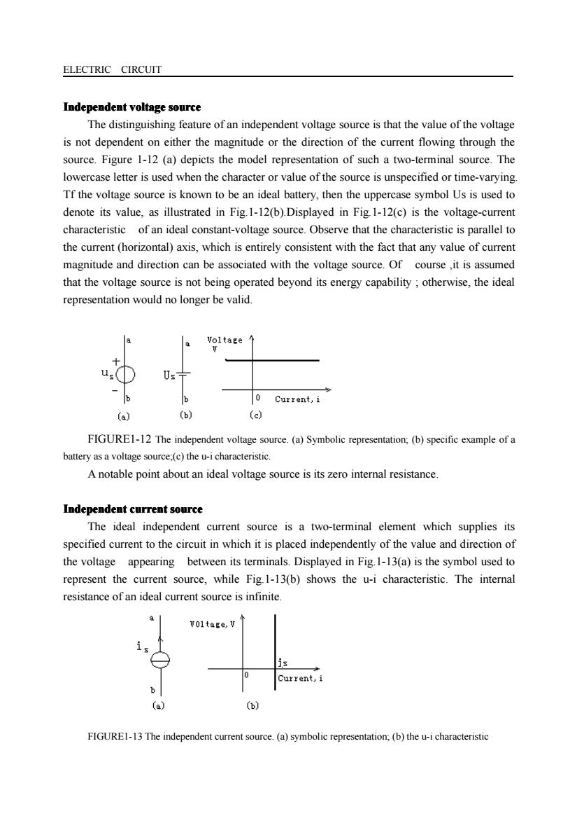
ELECTRIC CIRCUIT Independent Independent Independent Independent voltage voltage voltage voltage source The distinguishing feature of an independent voltage source is that the value of the voltage is not dependent on either the magnitude or the direction of the current flowing through the source. Figure 1-12 (a) depicts the model representation of such a two-terminal source. The lowercase letter is used when the character or value of the source is unspecified or time-varying. Tf the voltage source is known to be an ideal battery, then the uppercase symbol Us is used to denote its value, as illustrated in Fig.1-12(b).Displayed in Fig.1-12(c) is the voltage-current characteristic of an ideal constant-voltage source. Observe that the characteristic is parallel to the current (horizontal) axis, which is entirely consistent with the fact that any value of current magnitude and direction can be associated with the voltage source. Of course ,it is assumed that the voltage source is not being operated beyond its energy capability ; otherwise, the ideal representation would no longer be valid. FIGURE1-12 The independent voltage source. (a) Symbolic representation; (b) specific example of a battery as a voltage source;(c) the u-i characteristic. A notable point about an ideal voltage source is its zero internal resistance. Independent Independent Independent Independent current current current current source The ideal independent current source is a two-terminal element which supplies its specified current to the circuit in which it is placed independently of the value and direction of the voltage appearing between its terminals. Displayed in Fig.1-13(a) is the symbol used to represent the current source, while Fig.1-13(b) shows the u-i characteristic. The internal resistance of an ideal current source is infinite. FIGURE1-13 The independent current source. (a) symbolic representation; (b) the u-i characteristic
ELECTRIC CIRCUIT L-8 DEPENDENT (CONTROLLEDI SOURCES A dependent source is an active voltage or current source the output value of which is dependent upon another voltage or current.Dependent sources are also called controlled sources. There are essentially four basic types of dependent sources.One is the voltage-controlled voltage source (VCVS)shown as Fig.1-14(a).A second popular type is the current-controlled current source (CCCS)shown as Fig.1-14 (b).The common-emitter mode of the bipolar junction transistor amplifier is an outstanding example of this kind of controlled source; Fig.1-14(c)presents another alterative.The third type of dependent source involves a voltage-controlled current source (VCCS).This situation is often encountered when dealing with field-effect transistor amplifiers.Finally,the fourth type involves the control of voltage from a current source(CCVS)shown as Fig.1-14(d). (b) (e) FIGURE1-14 The controlled source (a)symbol of VCVS, (b)symbol of CCCS,(c)symbol of VCCS,(d)symbol of CCVS 19 KIRCHHOFF'S LAWS By the middle of the nineteenth century a considerable amount of experience with electric circuits had been gained by the leading men of science of the time.However it was Gustav Robert Kirchhoff(1824-1887)who published the first systematic formulation of the principles governing the behavior of electric circuits.His work was embodied in two laws-a current and a voltage law-which together are known as Kirchhoff's laws.It is upon these laws that electric circuit theory is based Kirchhoff's current law Kirchhoff's current law states that the sum of the currents entering or leaving a junction point at any instant is equal to zero. A junction point is that place in a circuit where two o more circuit elements are joined together.The current law may be expressed mathematically
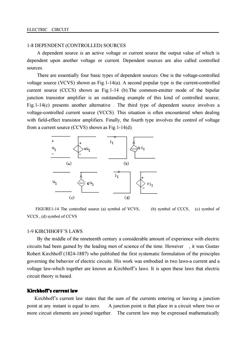
ELECTRIC CIRCUIT 1-8 DEPENDENT (CONTROLLED) SOURCES A dependent source is an active voltage or current source the output value of which is dependent upon another voltage or current. Dependent sources are also called controlled sources. There are essentially four basic types of dependent sources. One is the voltage-controlled voltage source (VCVS) shown as Fig.1-14(a). A second popular type is the current-controlled current source (CCCS) shown as Fig.1-14 (b).The common-emitter mode of the bipolar junction transistor amplifier is an outstanding example of this kind of controlled source; Fig.1-14(c) presents another alternative . The third type of dependent source involves a voltage-controlled current source (VCCS). This situation is often encountered when dealing with field-effect transistor amplifiers. Finally, the fourth type involves the control of voltage from a current source (CCVS) shown as Fig.1-14(d). FIGURE1-14 The controlled source (a) symbol of VCVS, (b) symbol of CCCS, (c) symbol of VCCS , (d) symbol of CCVS 1-9 KIRCHHOFF’S LAWS By the middle of the nineteenth century a considerable amount of experience with electric circuits had been gained by the leading men of science of the time. However , it was Gustav Robert Kirchhoff (1824-1887) who published the first systematic formulation of the principles governing the behavior of electric circuits. His work was embodied in two laws-a current and a voltage law-which together are known as Kirchhoff’s laws. It is upon these laws that electric circuit theory is based. Kirchhoff Kirchhoff Kirchhoff Kirchhoff’s current current current current law Kirchhoff’s current law states that the sum of the currents entering or leaving a junction point at any instant is equal to zero. A junction point is that place in a circuit where two or more circuit elements are joined together. The current law may be expressed mathematically