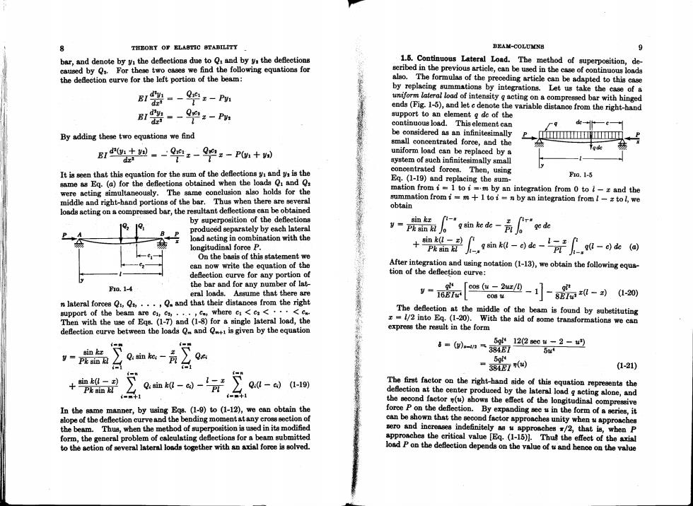
8 THEORY OF ELASTIC 8TABILITY BEAM-COLUMNS 9 bar,and denote by yi the deflections due to Q and by ya the deflections 1.5.Continuous Lateral Load.The method of superposition,de- caused by Q.For these two cases we find the following equations for seribed in the previous article,can be used in the case of continuous loads the deflection curve for the left portion of the beam: also.The formulas of the preceding article can be adapted to this case by replacing summations by integrations.Let us take the case of a B1器-4-Pm uniform lateral load of intensity g acting on a compressed bar with hinged ends (Fig.1-5),and let c denote the variable distance from the right-hand B1器---Pm: support to an element g de of the continuous load.This element can 9 By adding these two equations we find be considered as an infinitesimally small concentrated force,and the I← B1+n--吧x-2-P0+州 uniform lond ean be replaced by a system of such infinitesimally small It is seen that this equation for the sum of the deflections y and ya is the concentrated forces.Then,using Eq.(1-19)and replacing the sum- Fo.1-5 same as Eq.(a)for the deflections obtained when the loads Qi and Q were acting simultaneously.The same conclusion also holds for the mation from i=1 to i=m by an integration from 0 to i-z and the middle and right-hand portions of the bar.Thus when there are several summation fromi=m+I to i-n by an integration from /-z tol,we loads acting on a compressed bar,the resultant deflections can be obtained obtain by superposition of the deflections sin kx produced separately by each lateral y-Pk sin kl Jo 血ek-高Tg load acting in combination with the longitudinal force P. +in-到 Pk sin kl .9血0-dk-‘70-k回 On the basis of this statement we can now write the equation of the After integration and using notation(1-13),we obtain the following equa- deflection curve for any portion of tion of the deflection curve: ha.14 the bar and for any number of lat- g eral loads.Assume that there are y-16龙I [@c20--80-到a20 C08甚 n lateral forces Q,,...,Q and that their distances from the right support of the beam are c,cm.,.,,cn,where c<ca<···<cn The defleetion at the middle of the beam is found by substituting Then with the use of Eqs.(1-7)and (1-8)for a single lateral load,the z-1/2 into Eq.(1-20).With the aid of some transformations we can defection curve between the loads Q and is given by the equation express the reault in the form 5g12(2ec4-2-w9 sin kx Q 8=(-4n元384E7 5u y=Pk sin kl 5gl -38E) (1-21) sin k(l-) +Pk sin以 Qi sin k(l-ci) Q0-c)(1-19) The first factor on the right-hand side of this equation represents the defection at the center produced by the lateral load g acting alone,and the second factor()shows the effect of the longitudinal compressive In the same manner,by using Eqs.(1-9)to (1-12),we can obtain the force P on the deflection.By expanding sec u in the form of a series,it alope of tbe deflection curve and the bending moment at any croes section of can be shown that the second factor approaches unity when w approaches the beam.Thus,when the method of superposition is used in its modified sero and increases indefinitely as u approaches /2,that is,when P form,the general problem of caleulating deflections for a beam submitted approaches the critical value [Eq.(1-15)].Thus the effect of the axial to the action of several lateral loads together with an axial force is solved. load P on the deflection depends on the value of u and hence on the value
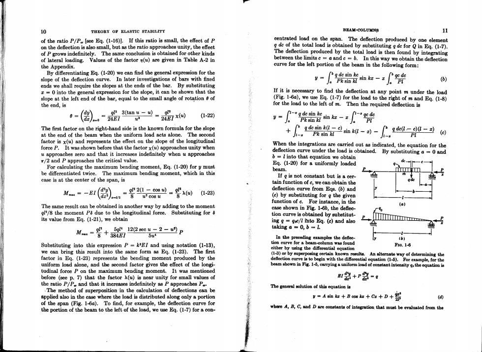
10 THEORY OF ELASTIC 8TABILITY BEAM-COLUMNB 11 of the ratio P/P [see Eq.(1-16)].If this ratio is small,the effect of P centrated load on the span.The deflection produced by one element on the deflection is also small,but as the ratio approaches unity,the effeet g de of the total load is obtained by substituting g de for in Eq.(1-7). of P growa indefinitely.The same conclusion is obtained for other kinds The deflection produced by the total load is then found by integrating of lateral loading.Values of the factorn(u)are given in Table A-2 in between the limits c a and c=b.In this way we obtain the deflection the Appendix. curve for the left portion of the beam in the following form: By differentiating Eq.(1-20)we can find the general expression for the g de sin ke」 slope of the deflection curve.In later investigations of bars with fixed y- J。Pk sin夏 f咖ka-x fgede (6) ends we shall require the slopes at the ends of the bar.By substituting z=0 into the general expression for the slope,it can be shown that the If it is necessary to find the deflection at any point m under the load slope at the left end of the bar,equal to the small angle of rotation 8 of (Fig.1-6a),we use Eq.(1-7)for the load to the right of m and Eq.(1-8) the end,is for the load to the left of m.Then the required deflection is 6= dy (1-22) -g de sin ke。 P%nH血杠一x fi-a ge de a The first factor on the right-hand side is the known formula for the slope + at the end of the beam when the uniform load acts alone.The second e9血kn--,-A0-丑因 Pk sin kl factor is x(u)and represents the effect on the slope of the longitudinal force P.It was shown before that the factor x(u)approaches unity when When the integrations are carried out as indicated,the equation for the u approaches zero and that it increases indefinitely when t approaches deflection curve under the load is obtained. By substituting a =0 and /2 and P approaches the critical value. b=2 into that equation we obtain For calculating the maximum bending moment,Eq.(1-20)for y must Eg.(1-20)for a uniformly loaded beam. P be differentiated twice.The maximum bending moment,which in this If g is not constant but is a cer- case is at the center of the span,is tain function of c,we can obtain the deflection curve from Eqs.(and Ma =-EI 2(1-c084) dzs 8u2c084 8A(侧 (1-23) (c)by substituting for g the given function of c.For instance,in the The same result can be obtained in another way by adding to the moment case shown in Fig.1-60,the deflec- ql/8 the moment P&due to the longitudinal force.Substituting for 8 tion curve is obtained by substitut- its value from Eq.(1-21),we obtain ing g=goc/7 into Eq.(c)and also 5g122sec4-2-w2P M-詈+ taking a =0,b=. I- 5u In the preceding examples the defleo- (B) Substituting into this expression P=kEI and using notation (1-13), tion eurve for a beam-column was found fa.1-6 we can bring this result into the same form as Eg.(1-23).The first either by using the differential equntion factor in Eg.(1-23)represents the bending moment produced by the (1-3)or by superpoeing certain known reaulta.An alternate way of determining the defleetion eurve is to begin with the diferential equntion (1-6).For example,for the uniform load alone,and the second factor gives the effect of the longi- beam shown in Fig.1-5,carrying a uniform load of constant intensity g the equntion is tudinal force P on the maximum bending moment.It was mentioned before (see p.7)that the factor A(u)is near unity for small values of r盖+P- the ratio P/P=and that it increases indefinitely as P approaches P.. The general solution of this equation is .The method of superposition in the calculation of deflections can be applied also in the case where the load is distributed along only a portion ,-Aaa+Bwu+Ca+D+器 of the span (Fig.1-6a).To find,for example,the deflection curve for the portion of the beam to the left of the load,we use Eq.(1-7)for a con- where A,B,C,and D are constanta of integration that must be evaluated from the
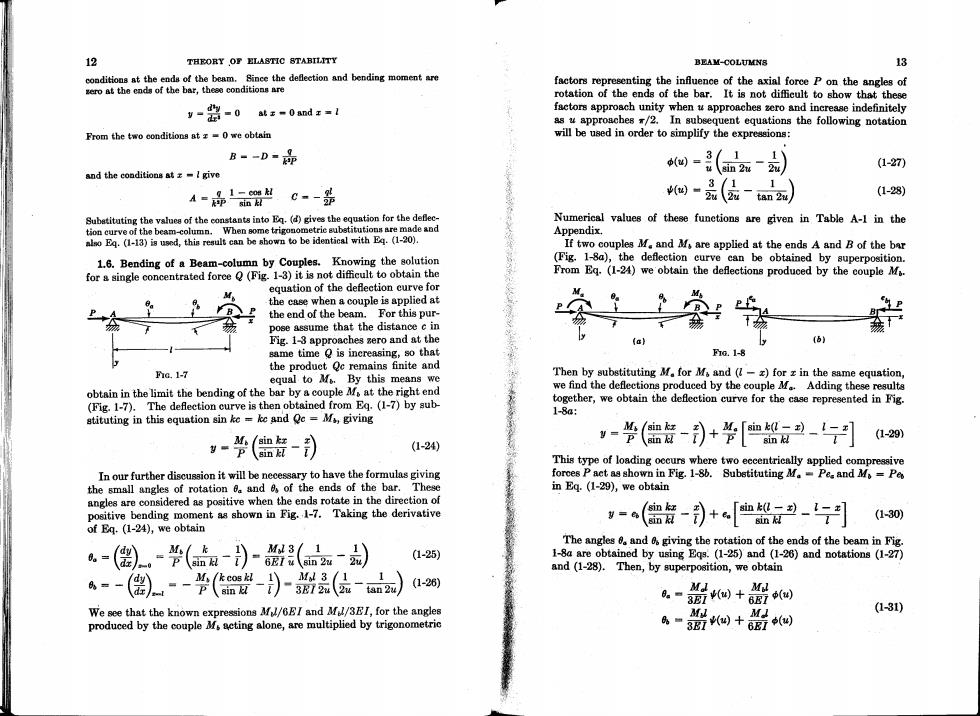
12 THEORY OF ELASTIC STABILITY BEAM-COLUMNS 13 conditions at the ends of the beam.Since the deflection and bending moment are factors representing the influence of the axial force P on the angles of ero at the ends of the bar,these conditions are rotation of the ends of the bar.It is not difficult to show that these y-器-0 at 0and z=l factors approach unity when u approaches zero and increase indefinitely as u approaches /2.In subsequent equations the following notation From the two oonditions at z=0 we obtain will be used in order to simplify the expressions: B--D- (=3 usin 2u 2u (1-27 and the conditions at z =I give 3/1 1 1-cos kl (1-28) A=師面 c-器 (o创"元(2拉一tan24 Subatituting the values of the constants into E.(d)gives the equntion for the deflec- Numerical values of these functions are given in Table A-1 in the tion curve of the beam-column.When some trigonometrie substitutions are made and Appendix. also Eq.(1-13)is used,this result can be shown to be identical with Eq.(1-20). If two couples M.and M are applied at the ends A and B of the bar 1.6.Bending of a Beam-column by Couples.Knowing the solution (Fig.1-8a),the deflection curve can be obtained by superposition. for a single concentrated foree Q(Fig.1-3)it is not difficult to obtain the From Eq.(1-24)we obtain the deflections produced by the couple Ms. equation of the deflection curve for the case when a couple is applied at the end of the beam.For this pur- pose assume that the distance c in Fig.1-3 approaches zero and at the same time is increasing,so that Frc.1-8 the produet Qc remains finite and Fic.1-7 equal to M.By this means we Then by substituting M.for Ms and (-z)for z in the same equation, obtain in the limit the bending of the bar by a couple M at the right end we find the deflections produced by the couple M.Adding these results (Fig.1-7).The deflection curve is then obtained from Eq.(1-7)by sub- together,we obtain the deflection curve for the case represented in Fig. stituting in this equation sin ke ke and Qc =M,giving 1-8a: (1-29) -(-) (1-24) -警(儡-)+华[如到月 This type of loading occurs where two eccentrically applied compressive In our further discussion it will be necessary to have the formulas giving forces P act as shown in Fig.1-8b.Substituting M.-Pes and Mo=Pe the small angles of rotation 6 and of the ends of the bar.These in Eq.(1-29),we obtain angles are considered as positive when the ends rotate in the direction of positive bending moment as shown in Fig.1-7.Taking the derivative =(僧贵-司+[恤月 (1-30) of Eq.(1-24),we obtain The angles 0.and 6 giving the rotation of the ends of the beam in Fig. M/k 1 1 0。= (a)-器( (1-25) 1-8a are obtained by using Eqs.(1-25)and (1-26)and notations (1-27) and (1-28).Then,by superposition,we obtain 0=- -(-)-品(- d型 (1-26) M.I Mil ■3四)+687(四 We see that the known expressions M/6EI and M/3EI,for the angles 6~盟+盟回 M (1-31) produced by the couple M acting alone,are multiplied by trigonometric
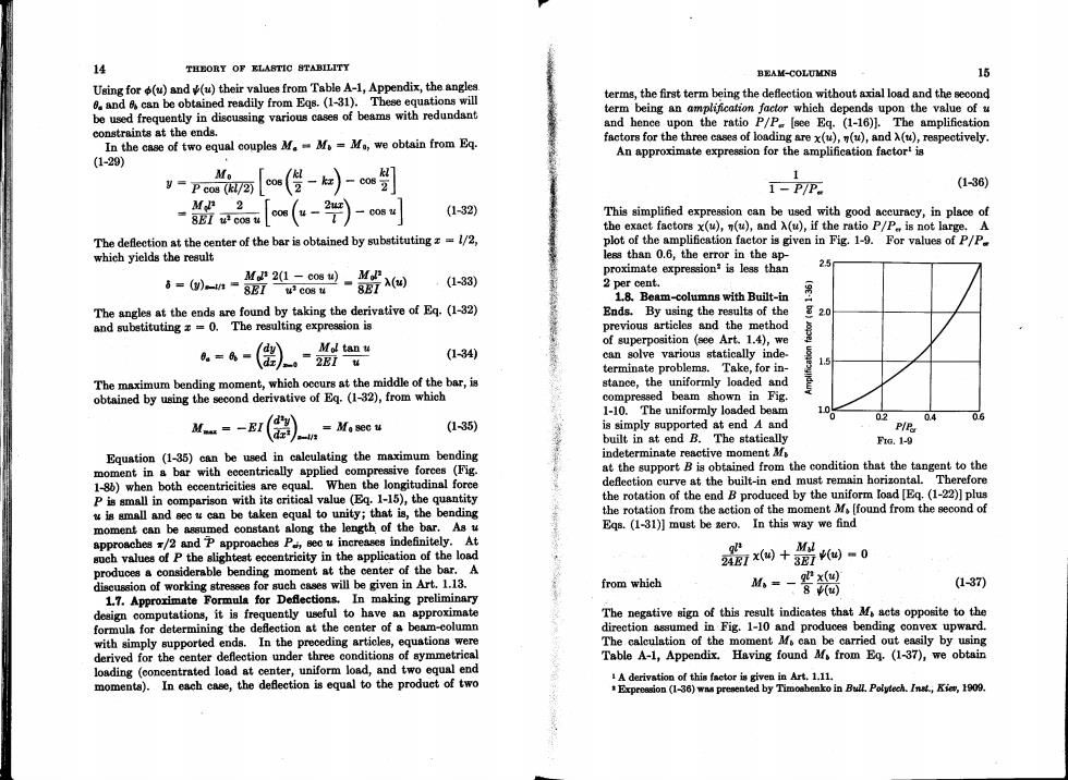
14 THEORY OF KLASTIC STABILITY BEAM-COLUMN8 16 Using for(u)and(u)their values from Table A-1,Appendix,the angles 0 and can be obtained readily from Eqs.(1-31).These equations will terms,the first term being the deflection without axial load and the second be used frequently in discussing various cases of beams with redundant term being an amplification factor which depends upon the value of u and hence upon the ratio P/P [see Eq.(1-16)].The amplification constraints at the ends. In the case of two equal couples MM=Mo,we obtain from Eq. factors for the three cases of loading are x(u),(u),and A(u),respectively. An approximate expression for the amplification factort is (1-29) Mo I=Pco8R72阿 co6(-Co6 1-P/P (136) M 2 -BBI u cos _2x\ cos(u-I C084 (1-32) This simplified expreasion can be used with good accuracy,in place of the exact factors x(u),n(u),and A(u),if the ratio P/P is not large.A The deflection at the center of the bar is obtained by substituting=1/2, plot of the amplification factor is given in Fig.1-9.For values of P/P. which yields the result less than 0.6,the error in the ap- proximate expression?is less than 6=()n= 2(1 cos u)) 8EI u cos u SE7(u) (1-33) 2 per cent. 1.8.Beam-columns with Built-in The angles at the ends are found by taking the derivative of Eq.(1-32) Ends.By using the results of the 号20 and subetituting z=0.The resulting expression is previous articles and the method dy Mol tan u of superposition (see Art.1.4),we (1-34) can solve various statically inde. terminate problems.Take,for in- The maximum bending moment,which occurs at the middle of the bar,is stance,the uniformly loaded and obtained by using the second derivative of Eq.(1-32),from which compressed beam shown in Fig. 1-10.The uniformly loaded beam dy 02 0.4 M.=-EI( dz =Ma sec u (135) is simply supported at end A and P/P built in at end B.The statically FG.1-9 Equation (1-35)can be used in calculating the maximum bending indeterminate reactive moment M moment in a bar with eccentrically applied compressive forces (Fig. at the support B is obtained from the condition that the tangent to the 1-8b)when both eccentricities are equal.When the longitudinal force deflection curve at the built-in end must remain horizontal.Therefore P is small in comparison with its critical value (Eq.1-15),the quantity the rotation of the end B produced by the uniform load [Eq.(1-22)]plus w is small and sec u can be taken equal to unity;that is,the bending the rotation from the action of the moment M[found from the second of moment can be assumed constant along the length of the bar.As u Eqs.(1-31)]must be sero.In this way we find approaches /2 and P approaches P sec u increases indefinitely.At M such values of P the slighteat eccentricity in the application of the load 24区7x侧+3Ew-0 produces a considerable bending moment at the center of the bar.A discussion of working stresses for such cases will be given in Art.1.13. from which 山=-器褐 (1-37) 1.7.Approximate Formula for Defections.In making preliminary design computations,it is frequently useful to have an approximate The negative sign of this result indicates that M acts opposite to the formula for determining the deflection at the center of a beam-column direction assumed in Fig.1-10 and produces bending convex upward. with simply supported ends.In the preceding articles,equations were The calculation of the moment Mf can be carried out easily by using derived for the center deflection under three conditions of symmetrical Table A-1,Appendix.Having found M.from Eq.(1-37),we obtain loading (concentrated load at center,uniform load,and two equal end moments).In each case,the deflection is equal to the produet of two A derivation of this factor is given in Art.1.11. Expreasion (1-36)was presented by Timosbenko in Bull.Polytech.Inst,Kie,1909
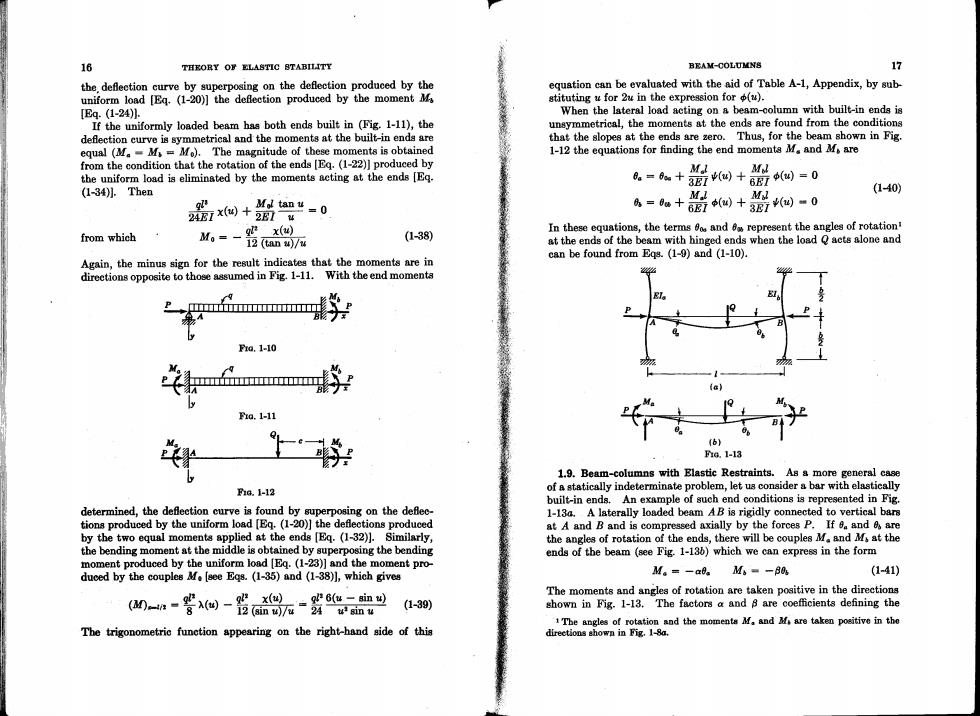
16 THEORY OF ELASTIC STABILITY BEAM-COLUMNS 17 the.deflection curve by superposing on the deflection produced by the equation can be evaluated with the aid of Table A-1,Appendix,by sub uniform load [Eq.(1-20)]the deflection produced by the momentM stituting u for 2u in the expression for (u). [Eq.(1-24)1. When the lateral load acting on a beam-column with built-in ends is If the uniformly loaded beam has both ends built in (Fig.1-11),the unsymmetrical,the moments at the ends are found from the conditions deflection curve is symmetrical and the moments at the built-in ends are that the slopes at the ends are zero.Thus,for the beam shown in Fig. equal (MM=Mo).The magnitude of these moments is obtained 1-12 the equations for finding the end moments M.and M.are from the condition that the rotation of the ends [Eq.(1-22)]produced by the uniform load is eliminated by the moments acting at the ends [Eq. =a+0+0侧=0 MI (1-34)1.Then Mol tan u =0 27x侧+2Eu A=u++0侧-0 M (1-40) from which M,=-器 In these equations,the terms o and represent the angles of rotation (1-38) at the ends of the beam with hinged ends when the load Q acts alone and can be found from Eqs.(1-9)and (1-10). Again,the minus sign for the result indicates that the moments are in directions opposite to those assumed in Fig.1-11.With the end momenta 9 na.1-10 1a.1-11 nG.1-13 1.9.Beam-columns with Elastic Restraints.As a more general case f1G.1-12 of a statically indeterminate problem,let us consider a bar with elastically built-in ends.An example of such end conditions is represented in Fig. determined,the deflection curve is found by superposing on the defec- 1-13a.A laterally loaded beam AB is rigidly connected to vertical bars tions produced by the uniform load [Eq.(1-20)]the deflections produced at A and B and is compressed axially by the forces P.If d.and are by the two equal moments applied at the ends [Eq.(1-32)].Similarly, the angles of rotation of the ends,there will be couples M.and M at the the bending moment at the middle is obtained by superposing the bending ends of the beam (see Fig.1-136)which we can express in the form moment produced by the uniform load [Eq.(1-23)]and the moment pro- duced by the couples M.[see Egs.(1-35)and (1-38)],which gives M。=-a0。M。=-8a (1-41) The moments and angles of rotation are taken positive in the directions -n-若--x盘 gl 6(u -sin u) (1-39) shown in Fig.1-13.The factors a and 8 are coefficients defining the 1The angles of rotation and the moments M.and M are taken positive in the The trigonometric function appearing on the right-hand side of this directions shown in Fig.1-8a