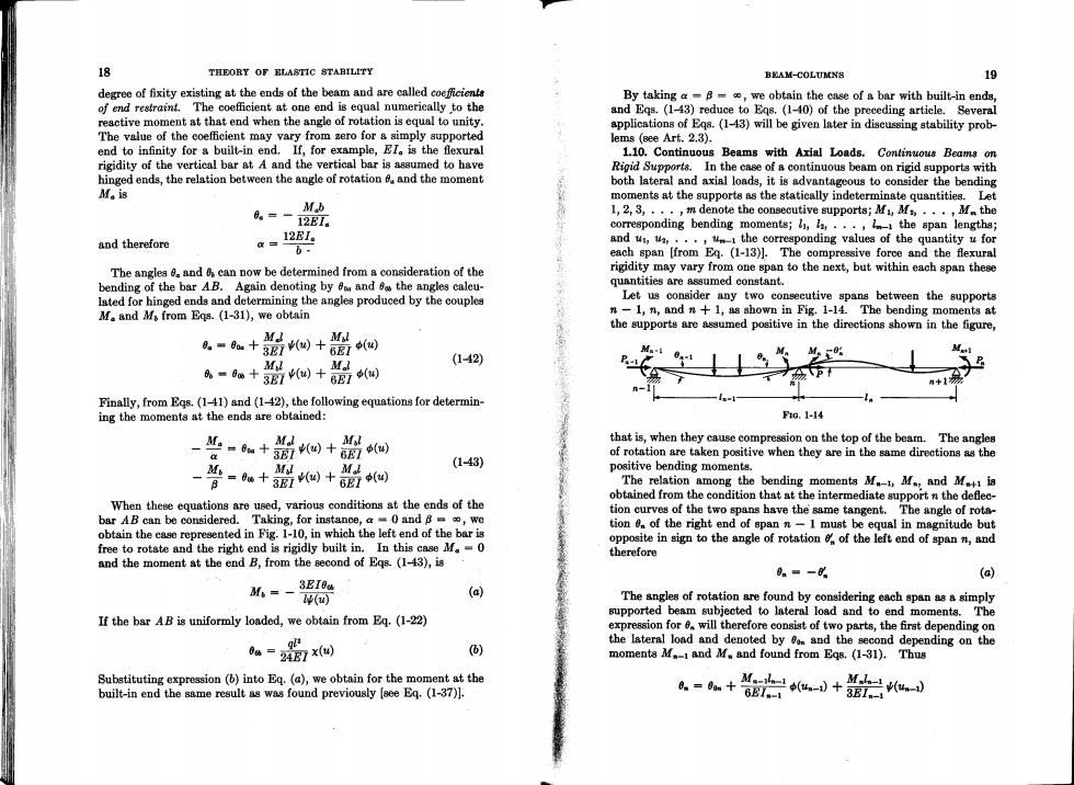
18 THEORY OF ELASTIC STABILITY BEAM-COLUMNS 19 degree of fixity existing at the ends of the beam and are called coeficiente By taking a-B-o,we obtain the case of a bar with built-in ends, of end restraint.The coefficient at one end is equal numerically to the and Eqs.(1-43)reduce to Eqs.(1-40)of the preceding article.Several reactive moment at that end when the angle of rotation is equal to unity. applications of Eqs.(1-43)will be given later in discussing stability prob- The value of the coefficient may vary from zero for a simply supported lems (see Art.2.3). end to infinity for a built-in end.If,for example,EI.is the flexural 1.10.Continuous Beams with Axial Loads.Continuous Beams on rigidity of the vertical bar at A and the vertical bar is assumed to have Rigid Supports.In the case of a continuous beam on rigid supports with hinged ends,the relation between the angle of rotation and the moment both lateral and axial loads,it is advantageous to consider the bending Ma is moments at the supports as the statically indeterminate quantities.Let M b 0。=-12E7. L,2,3,,·,m denote the consecutive supports;M,M,·,· Mthe corresponding bending moments;li,a,...,the span lengths; 12EI. and therefore a= and t,a,...,m-the corresponding values of the quantity u for b- each span [from Eq.(1-13)].The compressive force and the flexural The anglea 0.and 6 can now be determined from a consideration of the rigidity may vary from one span to the next,but within each span these bending of the bar AB.Again denoting by o and 6 the angles caleu- quantities are assumed constant. lated for hinged ends and determining the angles produced by the couples Let us consider any two consecutive spans between the supports M and Mo from Eqs.(1-31),we obtain n-1,n,and n+1,as shown in Fig.1-14.The bending moments at the supports are assumed positive in the directions shown in the figure, -u+o+品间 Mul M M.l (142) M %-8+3(u)+6E7(创 Finally,from Eqs.(1-41)and (1-42),the following equations for determin- -F-t ing the moments at the ends are obtained: FiG.1-14 “-+篇侧+6四 MI Mil that is,when they cause compression on the top of the beam.The angles of rotation are taken positive when they are in the same directions as the M=0+3Ei) M M (1-43) positive bending moments. 四+6E7(四 The relation among the bending moments M-1,M.,and M.+is obtained from the condition that at the intermediate support n the deflec- When these equations are used,various conditions at the ends of the tion curves of the two spans have the same tangent.The angle of rota- bar AB can be considered.Taking,for instanoe,a=0 and 8=,we obtain the case represented in Fig.1-10,in which the left end of the bar is tion 0 of the right end of span n-I must be equal in magnitude but opposite in sign to the angle of rotation of the left end of span n,and free to rotate and the right end is rigidly built in.In this case M=0 therefore and the moment at the end B,from the second of Eqs.(1-43),is 0n=- (a) M=-3EI0u () (a) The angles of rotation are found by considering each span as a simply supported beam subjected to lateral load and to end moments.The If the bar AB is uniformly loaded,we obtain from Eq.(1-22) expression for 8.will therefore consist of two parts,the first depending on the lateral load and denoted by m and the second depending on the 04=24E7x 6) moments M.-1 and M.and found from Eqs.(1-31).Thus Substituting expression (b)into Eq.(a),we obtain for the moment at the built-in end the same result as was found previously [see Eq.(1-37)1. .=+装启uW+ ML(u)
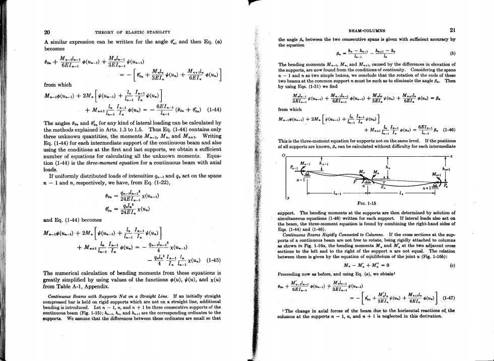
20 THEORY OF ELASTIC STABILITY BEAM-COLUMNS 21 A similar expression can be written for the angle and then Eq.(a) the angle between the two consecutive spans is given with suffcient accuracy by the equation becomes B-k。-k。_h1-h 例 M(un-1) M山-)+31。 - en+6B1.-1 The bending momente M.M and M causd by the differences in elevation of the supporta,are now found from the conditions of continuity.Considering the spans =- [+欲+0】 6EIn n-1 and n aa two simple beams,we conclude that the rotation of the ends of theae from which two beama st the common support n must be such as to eliminate the angle 8.Then by using Egs.(1-31)we find d+2w-[eu+台会0】 +Mn是会-2影+%)a4w 欲+会 +毫岩d+欲+e+管密a= -1 from which The angles o.and for any kind of lateral loading can be calculated by M.ead+2w[-d+之会0] the methods explained in Arts.1.3 to 1.5.Thus Eq.(1-44)contains only 上=-65=A.a48 three unknown quantities,the moments M1,M,and M Writing +M - Eq.(1-44)for each intermediate support of the continuous beam and also This is the three-moment equation for supports not on the same level.If the positions using the conditions at the first and last supports,we obtain a sufficient of all supporta are known,B.can be calculated without difficulty for each intermediate number of equations for calculating all the unknown moments.Equa- tion (1-44)is the three-moment equation for a continuous beam with axial loads. If uniformly distributed loads of intensities g and g act on the spans n-1 and n,respectively,we have,from Eq.(1-22), m+17 go-1 24E1。x%- 么一脸 10.1-15 support.The bending moments at the supports are then determined by solution of and Eq.(1-44)becomes simultaneous equstions (1-46)written for each support.If lateral loads also set on the beam,the three-moment equstion is found by combining the right-hand sides of -a+[+2会] Eqs(1-44)and(1-46). Continuous Beame Rigidly Connected to Columns.If the cross sections at the sup- 之会u)=-9='xu-d ports of a continuous beam are not free to rotate,being rigidly attached to columns +M+1I as sbown in Fig.1-16a,the bending momenta M.and Mf,at the two adjseent eroas sections to the left and to the right of the support n are not equal.The relation -以1=xu)45) between them is given by the equstion of equilibrium of the joint n(Fig.1-166): 4I。- M.-+M-0 () The numerical calculation of bending moments from these equations is Proceeding now as before,and using Eq.(a),we obtaint greatly simplified by using values of the functions (u),(),and x(u) from Table A-1,Appendix. +d+ 8BI.-1 M (u-1) 3E1.-1 Continuous Beams with Supports Not on a Straight Line.If an initinlly straight compressed bar is held on rigid supporta which are not on a straight line,additional [k+欲+0欲]a4切 bending is introdueed.Let n-1,n,and n+1 be three consecutive supports of the continuous besm (Fig.1-15);andare the correaponding ordinates to the 1The change in axial forces of the benm due to the horizontal resetions of the supporta.We aasume that the differences between these ordinates are al ao that columna at the supporta n-1,n,and n+1 is negleeted in this derivation
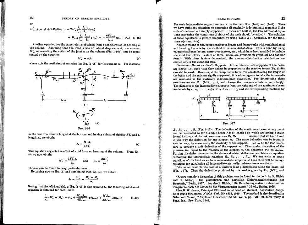
22 THEORY OF ELASTIC STABILITY BEAM-COLUMNS 23 or For each intermediate support we ean write the two Egs.(1-48)and (1-49).Thus td+2小+2台完 we have sufficient equations to determine all statically indeterminate moments if the ends of the beam are simply supported.If they are built in,the two additional equs- +M治会d-经a+6a4同 tions expressing the eonditions of fixity of the enda should be added.The solution l.-1 of theee equations is greatly simplified by using Table A-1,Appendix,for the fune- tions (u)and (w). Another equntion for the same joint is obtained from a consideration of bending of Another means of analysing continuoun beams and frameworks with combined axial the column.Assuming that the joint n has no lateral displacement,the moment and bending loads is by the method of moment distribution.This is done by using representing the aetion of the joint n on the column (Fig.1-16a),can be repre- valuca of stiffneas factors,carry-over factora,ete.,which have been modified to include sented by the equstion the axial load effeet.Values of theee factora are available in graphical and tabular M。=aA (d) form.With these factors determined,the moment-distribution ealculations are where a.is the coefficient of restraint [aee Eq.(1-41)]for the support n.For instance, earried out in the standard way. Continuots Beams on Elastic Supports.If the intermediate supports of the beam are elastic,ie.,such that they defleet in proportion to the reaetive forces,Eq.(1-46) can still be used.However,if the compresive force P is constant along the length of the beam and the ends are rigidly supported,it is advantsgeous to take the intermedi- ate reactions as the statieally indeterminate quantitiea.For determining thesc resetions we use Eq.(1-19),p.8,and change the previous notations sccordingly. The distances of the intermediste supporta from the right end of the continuous beam we denote by ca...,(e<c<e.),and the correspouding reactions by 11111113 a1 F1G.1-17 Fr0.1-16 B..,R.(Fig.1-17).The deflection of the continuous beam at any point in the case of a column hinged at the bottom and having a fexural rigidity EI and s can be calculated as for a simple beam AB of length I on whieh are seting a given length h.we obtain lsteral loading and the unknown reactions Ri,Ra,....Assume that we have found Mh in this way the deflection for any support m.The same defleetion ean be found in 8.-3BT. (e) another way,by considering the elasticity of the support.Let am be the load neces- sary to produce a unit deflection of the support m.Then under the action of the This equation negleets the effeet of axinl force on bending of the column.From Eq. pressure R,equnl to the resetion of the support m,the deflection will be'R/a (e)we now obtai山 Putting this defleetion equal to the above caleulated defection,we obtain an equstion M"SEIe containing the intermediate reactions R,...,R.We can write as many equntions of this kind as we have intermediate supports,so that there will be enough oquations for caleulating all intermedinte statieally indeterminste reactions. Thusa.can be found for any particular case. Take as an example the case of a uniform load g distributed along the beam AB Returning now to Eq.(d)and combining with Eq.(e),we obtnin (Fig.1-17).Then the defleetion produced by this load is given by Eq.(1-20),and 4-。M-M 1A very complete discussion of this problem can be found in the book by F.Bleich and E.Melsn,"Die gewonlichen und partiellen Differenzengleichungen der Baustatic,"Berlin,1927.See also F.Bleich,"Die Berechnung statisch unbestimmter Noting that the left-hand side of Eg.(1-47)is also equal to 8,the following additional Tragwerke nach der Methode des Viermomenten sstses,"2d ed.,Berlin,1925. equstion is obtained for ench joint: See B.W.James,Principal Effeeta of Axinl Load on Moment Distribution Analy- Mdu-小+3B1 上(-M)-m+6B (u-i) sis of Rigid Struetures,NACA Tech.Nole 534,1935.The method is also deecribed in (1-49) Niles and Newell,"Airplane Struetures,"3d ed.,vol.2,pp.120-132,John Wiley Sons,Ine.,New York,1943
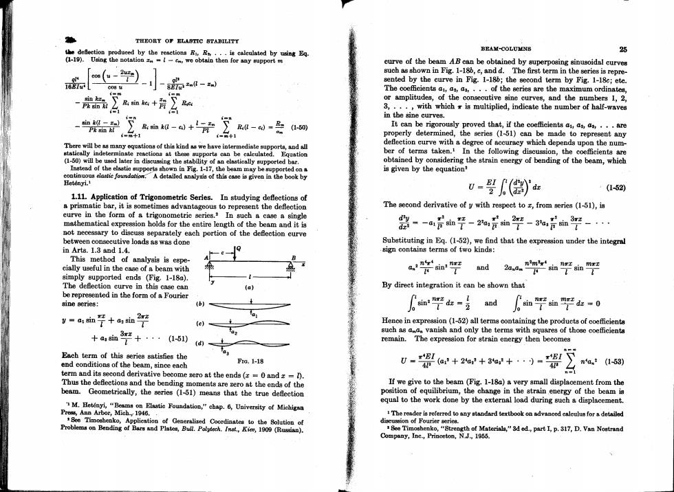
THEOBY OF ELASTIC BTABILITY the defection produced by the reactions Ri R...is caleulated by using Eq. BEAM-COLUMNS 25 (1-19).Uging the notation-c,we obtain then for any support m curve of the beam AB can be obtained by superposing sinusoidal curves (- such as shown in Fig.1-186,c,and d.The first term in the series is repre- ---小 sented by the curve in Fig.1-18b;the second term by Fig.1-18c;ete. 0帽4 The coefficients ,a,...of the series are the maximum ordinates, sin kr or amplitudes,of the conseoutive sine curves,and the numbers 1,2, Pk gin k 3,...,with which is multiplied,indicate the number of half-waves 血-裂】 Pk sin ,血0-+∑--是 in the sine curves. (1-50) It can be rigorously proved that,if the coefficients a,as aa,...are properly determined,the series (1-51)can be made to represent any There will be as many equations of this kind as we have intermediate supporte,and all deflection curve with a degree of accuracy which depends upon the num- statically indeterminate reactiona at these supporta can be calculated.Equation ber of terms taken.In the following discussion,the coefficients are (1-50)will be ued later in discuasing the stability of an elsstically supported bar. obtained by considering the strain energy of bending of the beam,which Instead of the elastie supports shown in Fig.1-17,the beam may be supported ona is given by the equation? continuous elafic foundation.A detailed analyais of this case is given in the book by Hetinyi.1 (1-52) 1.11.Application of Trigonometric Series.In studying deflections of u-婴(红 a prismatie bar,it is sometimes advantageous to represent the deflection The second derivative of y with respeet to z,from series (1-51),is curve in the form of a trigonometric series.In such a case a single -a后如平-2%后如2竿-%言血平 dy mathematical expression holds for the entire length of the beam and it is not necessary to discuss separately each portion of the deflection curve between consecutive loads as was done Substituting in Eq.(1-52),we find that the expression under the integral in Arts.1.8 and 1.4. sign contains terms of two kinds: This method of analysis is espe- cially useful in the case of a beam with a学m"平 and 2a.平血平 simply supported ends (Fig.1-18a). The deflection curve in this case can (a) By direct integration it can be shown that be represented in the form of a Fourier sine series: (b) 血平d女- 6 and 如7血平-0 y-1m7+am2竿 2x2 (e) Hence in expression (1-52)all terms containing the products of coefficients az such as aa vanish and only the terms with squares of those coefficients +a sin1 +···(1-51) d remain. The expression for strain energy then becomes Each term of this series satisfies the a end conditions of the beam,since each G.1-18 4r(a3+2a:+3a+:)=B 0=B1 na.(1-53) term and its second derivative become zero at the ends(x =0 and z =) Thus the deflections and the bending moments are zero at the ends of the If we give to the beam (Fig.1-18a)a very small displacement from the beam.Geometrically,the series (1-51)means that the true deflection position of equilibrium,the change in the strain energy of the beam is 1M.Hetenyi,"Beamn on Elastie Foundation,"chap.6,University of Michigan equal to the work done by the external load during such a displacement. Prens,Ann Arbor,Mich.,1946.. The reader is referred to any standard textbook on advaneed ealu fora detailed Bee Timoshenko,Applieation of Generalized Coordinates to the Solution of diseussion of Fourier serie8. Problemn on Bending of Bars and Plates,Bull.Polytech.Inst.,Kiev,1909 (Russian). Bee Timoshenko,"Strength of Materials,"3d ed.,part I,p.317,D.Van Nostrand Company,Ine.,Princeton,N.J.1955
28 THEORY OF ELASTIC STABILITY BEAM-COLUMNB 27 This follows from the principle of virtual displacements,and we shall use it in determining the coefficients of the series (1-51).Small displace- load,the values z =c=1/2 are substituted into Eq.(1-54),which gives ments of the beam from the position of equilibrium can be obtained by 6=(创)x-n■ 2Q1*/ 1 small variations of the coefficients,a,....If any coefficient a (1+苏+京+) is given an inerease da,we have the term (a.+da.)sin (nxx/t)in series The series is rapidly converging,and the first few terms give the deflec- (1-51)instead of the term a.sin (nrz/1).The other terms of the series tion with a high degree of accuracy.Using only the first term of the remain unchanged.Thus the increase da.in the coefficient a.represents series we obtain an additional small deflection of the beam given by the sine curve 6=2Q On da.sin E7=48.7B Comparison with the exact solution shows that we obtained 48.7 instead superposed upon the original deflection curve.The work done by the of 48 in the denominator of the expression.Thus the error in using only external load during this additional deflection can now be calculated. the first term of the series,instead of the entire series,is about 1 per cent. In the case of a single lateral load Q applied at the distance c from the left This accuracy is sufficient for many practical purposes. support (Fig.1-18a),the point of application of the load undergoes a The solution for a single load (Eq.1-54)having been obtained,other vertical displacement das sin (nxc/)and the load produces the work cases of loading can be solved by using the method of superposition. Consider,for instance,a beam carrying a uniformly distributed load of Qa.血吧 intensity g.Each increment of load,gde,at distance c from the left support ean be considered as a concentrated load,and the corresponding The change in strain energy [Eq.(1-53)]of the beam due to the increase defections,which we denote by dy,are obtained from Eq.(1-54)by sub- das in as is stituting g de for Q.Then 8肥a=aa dy -2g de t Equating the change in strain energy to the work done by the load,we obtain an equation for determining the coefficient a.: Integrating this expression with respeet to c,between the limits c=0 E 是na,=Q血平 and c=l,we obtain the deflection curve for the case when the uniform load is distributed along the entire span: from which 2Q1* a=血7 4gl = Substituting this expression for the coefficient a.in the series (1-51), PEI w13,, we obtain the equation for the deflection curve in the series form Again we obtain rapidly converging series.Taking,for instance,only 2Q18 y- the first term and calculating the deflection at the center,we find 6= 4gl 2Q10 1 元76.6B (1-54) The exact solution for this case gives Through use of this series,the deflection for any value of z can be 5g' calculated. 6=3847=76.887 As an example,let us consider the case in which the load is applied at the center of the span.In order to calculate the deflection under the Thus the error in taking only the first term is less than one-half of I per cent in this case