
xiv CONTENTS 11.6 Bent or Eooentrically Compressed Cylindrical Shells. 482 11:7 Axial Compression of Curved Sheet Panels 485 11.8 Curved Sheet Panels under Shear or Combined Shear and Axial Stree 11.9 Buckling ofStitfened Cylindricnl Shell under Axial Compreesion.. 48 11.10 Buekling of a Cylindrical Shell under Combined Axial and Uniform Lateral Pressure . 495 11.11 Buckling of a Cylindrical Shell Bubjeeted to Torsion.. 500 11.12 Buckling of Conical Shells . 509 11.13 Buckling of Uniformly Compreed Spherical Sbeils 612 NOTATIONS pnh,,。。。,,+。··,。····”· 521 Table A-1.Table of the Funetions),),x(). 4 521 a,b,c,d Numerical coefficienta,distances Table A-2.Table of the Functiona()and () 629 A Cross-nectional ares Table A-3.Properties of8 ections,,,·· 530 Distance from neutral axis to extreme fiber of beam 631 C Toreional rigidity (C-GJ) Name Index.‘.,',,-. C Warping rigidity (C BC.) Subject Index 4 535 C. Warping constant D Flexural rigidity of plate or shell [D Eh/12 (1-) Eocentricity,distance from centroid to shear center B.E,E Modulus of elaaticity,roduced modulus,tangent modulus Streas function Acceleration of gravity Modulus of clasticity in shear Thickness of plate or shell,height,distance Polar moments of inertia of a plane ares with respect to centroid and ahear center I Iy I Moments of inertis ofa plane area with respect to ,and axe Produet of inertia of a plane ares with respeet to a and y axes Torsion constant Axial losd faetor for beam-columns (k-P/BI),modulus of clastic foundation,numerieal faetor 【c知gth,8pBD L Redueed length ,作 Integers,numerical factors Intenity of torque per unit distance alongaxis Bending moment,couple M. Twisting couple or torque M.My Mev Bending and twisting momenta per unit distance in plate or shell Faetor of safety Shearing force in beam,normal force N.Nu N. Normal snd shearing forces per unit distance in middle surface of plate or shell 月9 Intenaity of distributed load,preasure P Concentrated foree,axial foree in beam-column Critical buckling load Q Shearing force in beam,conoentrated foree 0Q Sbearing forees per unit distance in plate or shell Radius of gyration,radius of curvature of shell,radius R Radins,reactive foree 8 Core radius (s -2/A),distanee 8 Axial force W

xvi NOTATIONB Thiekness,time,temperature Work,tenaile foree Axisl load factor for beam-columns (u/2) ,, Displacementa in多,,and z directions U Btrain energy 可,0 Displacements in tangential and radial directions CHAPTER 1 y Shearing foree in beam Warping displacement in beam BEAM-COLUMNS ,多 Rectangular coordinates Section modulus (2=I/e) 1.1.Introduction.In the elementary theory of bending,it is found that stresses and deflections in beams are directly proportional to the restraint applied loads.This condition requires that the change in shape of the y Shearing unit strain,weight per unit volume,spring conatant, beam due to bending must not affect the action of the applied loads. numerical factor For example,if the beam in Fig.1-la is subjected to only lateral loads, 8 Defection Unit normal strain,coefficient of thermal expansion such as Q amd Qa,the presence of the small deflections 61 and and slight , Unit normal strains in z,y,and s directionn changes in the vertical lines of action of the loads will have only an insig- Amplifcation factors for beam-columns nificant effect on the moments and shear forces.Thus it is possible to Angle,angulnr coordinate,angle of twist per unit length make calculations for deflections,stresses,moments,ete.,on the basis of Distance,numerical factor Poisson's ratio the initial configuration of the beam.Under these conditions,and also 名男下 Reetangular coordinates if Hooke's law holds for the material,the deflections are proportional to Radius of curvature the acting forces and the principle of superposition is valid;Le.,the final Unit normal streas deformation is obtained by summation of the deformations produced by Ua dn ds Unit normal stresses in z,y,and directions the individual forces. 4 Average compresaive unit atreas for columns Compreesive unit streas at critical load Conditions are entirely different when both axial and lateral loads act olt Unit streas at ultimate load simultaneously on the beam (Fig.1-16).The bending moments,shear Working unit streas forces,stresses,and deflections in the beam will not be proportional to Yield-point streas the magnitude of the axial load.Furthermore,their values will be Unit shear stres dependent upon the magnitude of the deflections produced and will be Te,T南Tu Unit shear stresses on planes perpendicular to the馬,斯,and&axes and sensitive to even alight eccentricities in the application of the axial load. parallel to the y,美,8od¥axw Angle,angular coordinate,angle of twist of bar Beams subjected to axial compression and simultaneously supporting X Change of curvature in shell lateral loads are known as beam-columns.In this first chapter,beam- Radian froquency of vibration columns of symmetrical cross section and with various conditions of Warping function support and loading will be analyzed. 1.2.Differential Equations for Beam-columns.The basic equations for the analyais of beam-columns can be derived by considering the beam in Fig.1-2a.The beam is subjected to an axial compressive force P and to a distributed lateral load of intensity g which varies with the dis- tance z along the beam.An element of length dz between two cross sections taken normal to the original (undeflected)axis of the beam is 1 For an analysis of beama subjected to axial tension see Timoshenko,"Strength of Materials,"3d od.,part II,p.41,D.Van Nostrand Company,Ine.,Princeton,N.J. 1966
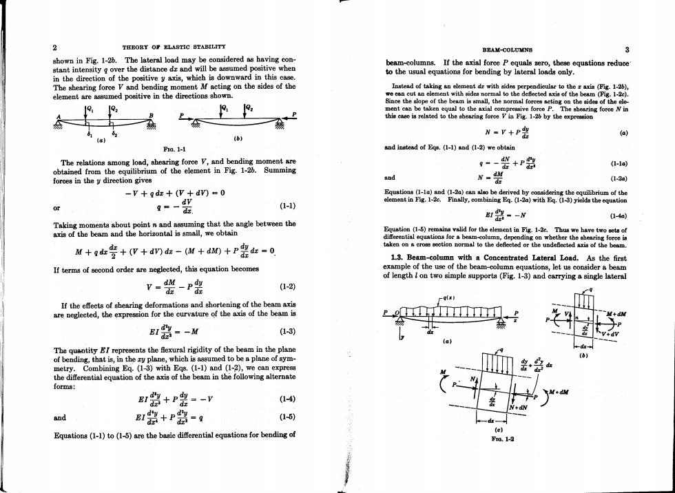
% THEORY OF ELASTIC STABILITY BEAM-COLUMNS shown in Fig.1-2b.The lateral load may be considered as having con- stant intensity g over the distance da and will be assumed positive when beam-columns.If the axial force P equals zero,these equstions reduce in the direction of the positive y axis,which is downward in this case. to the usual equations for bending by lateral loads only. The shearing force V and bending moment Mf acting on the sides of the Instead of taking an element d=with sides perpendicular to the axis (Fig.1-2), element are assumed positive in the directions shown. we can cut an element with sides normal to the deflected axis of the beam (Fig.1-2c). Since the slope of the beam is small,the normal forees neting on the sides of the ele- 12, ment can be taken equal to the axial compressive foree P.The shearing force N in this cae is relsted to the ahearing force V in Fig.1-26 by the expresaion (b) N-r+P器 @) (a) hg.1-1 nd instead of Egs.(1-1)and (1-2)we obtain The relations among load,shearing foroe V,and bending moment are (-1a obtained from the equilibrium of the element in Fig.1-20.Summing g-器+P器 forces in the y direction gives and N- (1-2a) -v+qdz+(V+dv)=0 Equstions(1-1a)and(1-2)can also be derived by considering the equilibrium of the element in Fig.1-2c.Finally,combining Eq.(1-2a)with Eq.(1-3)yields the equstion or 9=- dt. (1-1) 数尝-N (1-4aj Taking moments about point n and assuming that the angle between the axis of the beam and the horizontal is small,we obtain Equstion (1-5)remains valid for the element in Fig.1-2c.Thus we have two seta of differential equations for s beam-column,depending on whether the shearing force is M+ga警+(v+am-(M+d0+P费-0 taken on s eross section normal to the deflected or the undeflected axis of the beam. 1.3.Beam-column with a Concentrated Lateral Load.As the first If terms of second order are neglected,this equation becomes example of the use of the beam-column equations,let us consider a beam of length I on two simple supports(Fig.1-3)and carrying a single lateral v-器-P器 (1-2) If the effects of shearing deformations and shortening of the beam axis are neglected,the expression for the curvature of the axis of the beam is 1碧=-M (1-3) The quantity BI represents the fexural rigidity of the beam in the plane of bending,that is,in the ry plane,which is assumed to be a plane of sym- metry.Combining Eq.(1-3)with Eqs.(1-1)and (1-2),we can express the differential equation of the axis of the beam in the following alternate forms: B路+P鼎=-V (1-4) and BI器+P器-g (1-5) (e) Equations(1-1)to (1-5)are the basie differential equations for bending of Fro.1-2

THEORY OF ELASTIC BTABILITY BEAM-COLUMNB 5 load Q at distance c from the right end.The bending moments lue to the mon tangent.These conditions give lateral load Q,if acting alone,could be found readily by statics.How- ever,in this case the axial force P causes bending moments which can- B血机-0-%a-g not be found until the deflections are determined.The beam-column =Dsn机-)-tan-l-号Q-0 is therefore statically indetermi- nate,and it is necessary to begin by B张cosk机-)- solving the differential equation for Fg.1-3 the deflection curve of the beam. -DHtcos k(-)tan kl sin k()) P The bending momenta in the left-and right-hand portions of the beam from which Q sin ke in Fig.1-3 are,respectively, B=Pkim对 D=-Qink0-c) Pk tan ) M-号:+mM-90-9Q-9+Pm Substituting into Egs.(c)and (d)the values of the constants from (e) and,therefore,using Eq.(1-3)we obtain and (f),we obtain the following equations for the two portions of the deflection curve: B1---Pm (a) 1路--0-0-丑-Pm y=领血u-资:0sz≤1-0 (1-7) () y-Q血地-d血h机--0-e0-91-6≤x≤1 Pk sinl For simplification the following notation is introduced: (1-8) P k= (1-6) It is seen that Eq.(1-8)can be obtained from Eq.(1-7)by substituting -c for c and -x for z. and then Eq.(a)becomes By differentiation of Eqs.(1-7)and (1-8)the following formulas,useful 器+灼一品: Qc in later calculations,are obtained: dy Q sin ke The general solution of this equation is dz 品经mu-器 = 0≤x≤1-c(1-9) y=Ac在十B面好一气: (c) =-Qk:9osk0-)+g001-c≤z≤1 dz P sin kl (1-10) In the same manner the general solution of Eq.(6)is dy i=- 华血a 0≤x≤1-e(1-11) y=Coos缸十D gin kx- Q0-c0- Pl (④ dy dz Qk sink(-)sin k(-到 P ainl 1-c≤x≤1(1-12) The constants of integration A,B,C,and D are now determined from the conditions at the ends of the beam and at the point of applieation of In the particular case of a load applied at the center of the beam,the the load Q.Since the deflections at the ends of the bar are zero,we deflection curve is symmetrical and it is necessary to consider only the conclude that portion to the left of the load.The maximum deflection in this case is A =0 C=-D tan kl (e) obtained by subatituting x=c=1/2 in Eq.(1-7),which gives At the point of applieation of the load Q the two portions of the defleetion curve,as given by Eqs.(c)and (d),have the same deflection and a com- )

BEAM-COLUMNS 6 THEORY OF ELASTIC BTABILITY 7 To simplify this equation the following additional notation will be used: Again,the first factor is the slope produced by the lateral lond Q acting alone at the center of the beam and the second factor represents the effect 以1P (1-13) of the axial load P.Values of the factor A(u)are given in Table A-2 “=2=2VE7 of the Appendix. Then Eq.(g)becomes By using Eq.(1-11)we obtain the maximum bending moment as follows: 8贺7--%7x侧 &=481 (1-140 M--EI dy八 k以QI tan u dr* 2Ptan2-4 (1-18) The first factor on the right-hand side of this equation represents the deflection which is obtained if the lateral load Q acts alone.The second The maximum bending moment is obtained in this case by multiplying factor,x(u),gives the influence of the longitudinal force P on the deflec- the bending moment produced by the lateral load by the factor (tan u)/u. tion 8.Numerical values of the factor x(u)for various values of the The value of this factor,as well as the previous trigonometric factors quantity tare given in Table A-1 in the Appendix.By using this table, A()and x(u),approaches unity as the compressive force becomes the deflections of the bar can be calculated readily in each particular case smaller and smaller and increases indefinitely when the quantity u from Eq.(1-14). approaches r/2,that is,when the compressive foroe approaches the When P is small,the quantity u is also small [see Eq.(1-13)]and the critical value given by Eq.(1-15). factor x(u)approaches unity.This can be shown by using the series 1.4.Several Concentrated Loads.The results of the previous article will now be used in the more general case of several lateral loads acting on 如=+号+答+… the compressed beam.Equations (1-7)and (1-8)show that for a given longitudinal force the deflections of the bar are proportional to the and retaining only the first two terms of this series.It is seen alao that lateral load Q.At the same time the relation between defections and x(u)becomes infinite when u approaches x/2.When u=x/2,we find the longitudinal force P is more complicated,sinee this force enters into from Eq.(1-13) the trigonometric functions containing k.The fact that deflections are p linear functions of Q indicates that the principle of superposition,which (1-15) is widely used when lateral loads act alone on a beam,can also be applied in the case of the combined action of lateral and axial loads,but in a some- Thus it can be concluded that when the axial compressive force what modified form.It is seen from Eqs.(1-7)and (1-8)that,if we approaches the limiting value given by Eq.(1-15),even the smallest increase the lateral load Q by an amount Q,the resultant deflection is lateral load will produce considerable lateral deflection.This limiting obtained by superposing on the deflections produced by the load Q the value of the compressive force is called the critical load and is denoted deflections produced by the load Q,provided the same axial force acta by P By using Eq.(1-15)for the critical value of the longitudinal on the bar. force,the quantity u[see Eq.(1-13)]can be represented in the following It can be shown that the method of superposition can be used also if form: several lateral loads are acting on the compressed bar.The resultant (1-16) deflection is obtained by using Eqs.(1-7)and (1-8)and superposing the separate deflections produced by each lateral load aeting in combination with the total axial force.Take the case of two lateral loads Q1 Thus u depends only on the magnitude of the ratio P/P To find the slope of the deflection curve at the end of the beam,we and Q at the distances c and cs from the right support (Fig.1-4). Proceeding as in the previous article,we find that the differential equation substitute c =1/2 and z=0 into Eq.(1-9),which gives of the deflection curve for the left portion of the beam(sI-ca)is Q1 r路=-9z-9a-Py (a) Q2(1-c0s4) Q =16E7w2co8“ =16E7A (1-170 Now consider the loads Q,and Q:acting separately on the compressed