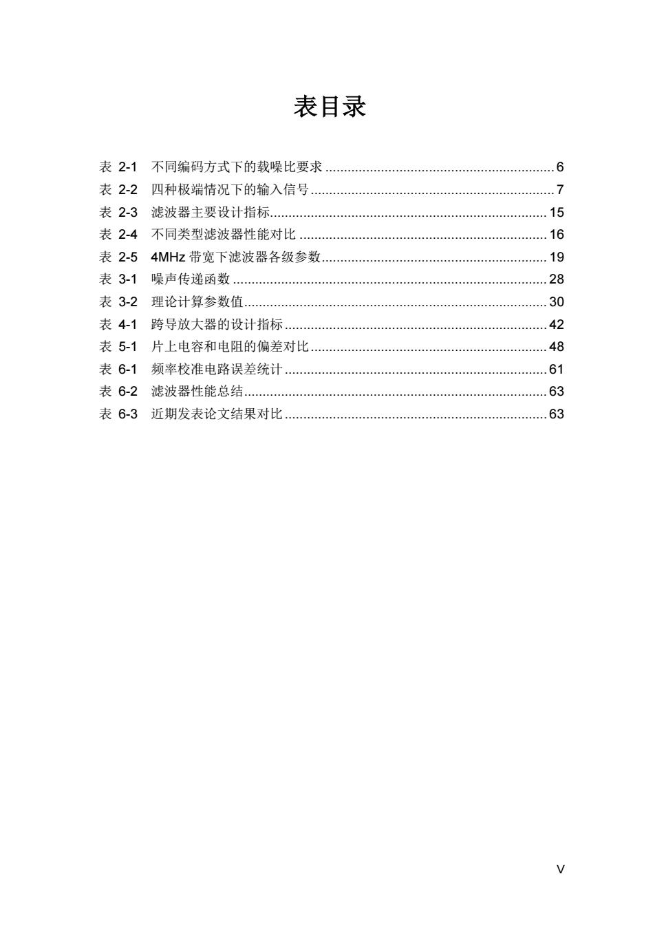
表目录 表2-1不同编码方式下的载噪比要求.… .6 表2-2四种极端情况下的输入信号 .7 表2-3滤波器主要设计指标 .15 表2-4不同类型滤波器性能对比 16 表2-54MHz带宽下滤波器各级参数..… 19 表3-1噪声传递函数 28 表3-2理论计算参数值 30 表4-1跨导放大器的设计指标… 42 表5-1片上电容和电阻的偏差对比 48 表6-1频率校准电路误差统计 61 表6-2滤波器性能总结. 63 表6-3近期发表论文结果对比.… 63
V 表目录 表 2-1 不同编码方式下的载噪比要求 .............................................................. 6 表 2-2 四种极端情况下的输入信号.................................................................. 7 表 2-3 滤波器主要设计指标........................................................................... 15 表 2-4 不同类型滤波器性能对比 ................................................................... 16 表 2-5 4MHz 带宽下滤波器各级参数............................................................. 19 表 3-1 噪声传递函数 ..................................................................................... 28 表 3-2 理论计算参数值.................................................................................. 30 表 4-1 跨导放大器的设计指标....................................................................... 42 表 5-1 片上电容和电阻的偏差对比................................................................ 48 表 6-1 频率校准电路误差统计....................................................................... 61 表 6-2 滤波器性能总结.................................................................................. 63 表 6-3 近期发表论文结果对比....................................................................... 63

摘要 移动数字电视调谐器需要具有出色的信道选择特性,以保证其具有从众多干 扰信号中将有用信号筛选出来的功能。本文围绕线性度和噪声优化、多带宽、可 变增益、截止频率校准等几方面,介绍了一款用于数字电视调谐器中的高线性度, 增益可调,带宽可调的信道选择滤波器。 本文完成的主要工作如下: 首先,本文详细讨论了如何对滤波器参数进行优化的设计方法。运用参数归 一化的方法,将多变量的最优化问题转换成单变量的最优化问题。这不仅简化了 优化过程,同时也使得结果更富有参考意义。基于这一方法,对有源RC双二次 结构级联滤波器的噪声和线性度进行优化设计。 其次,设计实现了带宽和增益可调的功能并解决了由非理想效应所引起的增 益误差和带内纹波问题。多标准多频段的应用要求信道选择滤波器具有带宽可调 的特性:而输入信号较大的动态范围需要模拟基带提供足够的增益变化范围以优 化输出信号的信噪比。设计中通过切换电阻阵列中的电阻和电容阵列中的电容来 实现多频带的选择和增益调节。改进的电阻匹配阵列使增益误差在整个增益范围 内得到有效控制。根据不同增益对分段电阻的调节来补偿品质因素的恶化减小了 高增益下的带内纹波。双二次结构中通过运用高增益、高线性度的前馈零点补偿 型跨导放大器来增加滤波器的线性度,同时避免了额外补偿电容的使用,减小了 芯片面积。 最后,对原有频率校准电路进行了改进。改进后的频率校准电路使得对由于 工艺偏差所造成的频率偏移的校准更加高效。所设计的直流偏移消除电路克服了 直接变频接收机中存在的直流失调问题。 测试结果显示,滤波器的带内P3在0dB增益时超过31dBm,增益范围 0~54dB,增益步长6dB,频率范围从0.25MHz~4MHz连续可调。高增益时, 带内纹波小于1.4dB,增益误差和频率校准误差分别小于3.4%和5%。该设计在 0.18-m CMOS工艺下制造,1.8伏供电电压下功耗为12.6mW,面积1.28mm2。 关键词:信道选择滤波器、高线性度、增益可调、多频带、连续可调、数字电视 调谐器 中图分类号:TN4 VII
VII 摘 要 移动数字电视调谐器需要具有出色的信道选择特性,以保证其具有从众多干 扰信号中将有用信号筛选出来的功能。本文围绕线性度和噪声优化、多带宽、可 变增益、截止频率校准等几方面,介绍了一款用于数字电视调谐器中的高线性度, 增益可调,带宽可调的信道选择滤波器。 本文完成的主要工作如下: 首先,本文详细讨论了如何对滤波器参数进行优化的设计方法。运用参数归 一化的方法,将多变量的最优化问题转换成单变量的最优化问题。这不仅简化了 优化过程,同时也使得结果更富有参考意义。基于这一方法,对有源 RC 双二次 结构级联滤波器的噪声和线性度进行优化设计。 其次,设计实现了带宽和增益可调的功能并解决了由非理想效应所引起的增 益误差和带内纹波问题。多标准多频段的应用要求信道选择滤波器具有带宽可调 的特性;而输入信号较大的动态范围需要模拟基带提供足够的增益变化范围以优 化输出信号的信噪比。设计中通过切换电阻阵列中的电阻和电容阵列中的电容来 实现多频带的选择和增益调节。改进的电阻匹配阵列使增益误差在整个增益范围 内得到有效控制。根据不同增益对分段电阻的调节来补偿品质因素的恶化减小了 高增益下的带内纹波。双二次结构中通过运用高增益、高线性度的前馈零点补偿 型跨导放大器来增加滤波器的线性度,同时避免了额外补偿电容的使用,减小了 芯片面积。 最后,对原有频率校准电路进行了改进。改进后的频率校准电路使得对由于 工艺偏差所造成的频率偏移的校准更加高效。所设计的直流偏移消除电路克服了 直接变频接收机中存在的直流失调问题。 测试结果显示,滤波器的带内 IIP3 在 0 dB 增益时超过 31 dBm,增益范围 0~54 dB,增益步长 6 dB,频率范围从 0.25 MHz~4 MHz 连续可调。高增益时, 带内纹波小于 1.4 dB,增益误差和频率校准误差分别小于 3.4%和 5%。该设计在 0.18-μm CMOS 工艺下制造,1.8 伏供电电压下功耗为 12.6 mW,面积 1.28 mm2。 关键词:信道选择滤波器、高线性度、增益可调、多频带、连续可调、数字电视 调谐器 中图分类号:TN4

Abstract The function that choosing wanted signal from numerous interferences of mobile TV Tuner is guaranteed by its excellent channel selection property. Focusing on issues such as linearity and noise optimization,multiple bandwidth, variable gain,cutoff frequency tuning and so on,this thesis presents a channel select filter used in TV Tuner with high linearity,variable gain and adjustable bandwidth characteristic. The main works of this thesis are as following: First,the design methodology for optimizing filter parameters is discussed in detail.A multivariable optimization problem is converted to a univariate optimization problem by using parameter normalization approach.This method not only simplifies the optimization process but also gets a more intuitionistic result.Linearity and noise performance of Active-RC cascade biquad is optimized basing on this method. Second,the design realizes adjustable bandwidth and gain and solves the problem of gain error and in band ripple caused by non-ideal effect. Multi-standard and multi-band application requires adjustable band width of the channel select filter.While the big dynamic range of input power requires the base band to have enough gain variation range for optimization the SNR (Signal Noise Ratio)of output signal.Band selection and gain adjustment are realized by switching resistors in resistor arrays and capacitors in capacitor arrays in this design.The revised match resistor array makes gain error effectively controlled in the whole gain range.Tuning segmented resistor according different gain to compensate Q (Quality)factor degradation decreases in band ripple under high gain.FFZC (Feed Forward Zero Compensation)OTA with high gain and high linearity is used in biquad to increase the linearity performance of filter while avoiding extra compensation capacitors use. Third,improve the frequency tuning circuit.The correction on frequency shift due to process variation is more efficient by using the improved frequency tuning circuit.DC offset problem in DCR (Direct Conversion Receiver)is prohibited by DC offset cancellation circuit. X
IX Abstract The function that choosing wanted signal from numerous interferences of mobile TV Tuner is guaranteed by its excellent channel selection property. Focusing on issues such as linearity and noise optimization, multiple bandwidth, variable gain, cutoff frequency tuning and so on, this thesis presents a channel select filter used in TV Tuner with high linearity, variable gain and adjustable bandwidth characteristic. The main works of this thesis are as following: First, the design methodology for optimizing filter parameters is discussed in detail. A multivariable optimization problem is converted to a univariate optimization problem by using parameter normalization approach. This method not only simplifies the optimization process but also gets a more intuitionistic result. Linearity and noise performance of Active-RC cascade biquad is optimized basing on this method. Second, the design realizes adjustable bandwidth and gain and solves the problem of gain error and in band ripple caused by non-ideal effect. Multi-standard and multi-band application requires adjustable band width of the channel select filter. While the big dynamic range of input power requires the base band to have enough gain variation range for optimization the SNR (Signal Noise Ratio) of output signal. Band selection and gain adjustment are realized by switching resistors in resistor arrays and capacitors in capacitor arrays in this design. The revised match resistor array makes gain error effectively controlled in the whole gain range. Tuning segmented resistor according different gain to compensate Q (Quality) factor degradation decreases in band ripple under high gain. FFZC (Feed Forward Zero Compensation) OTA with high gain and high linearity is used in biquad to increase the linearity performance of filter while avoiding extra compensation capacitors use. Third, improve the frequency tuning circuit. The correction on frequency shift due to process variation is more efficient by using the improved frequency tuning circuit. DC offset problem in DCR (Direct Conversion Receiver) is prohibited by DC offset cancellation circuit

Experimental results yield an in band //P3 of over 31 dBm at 0 dB gain,a 54 dB gain range with 6 dB gain step and a continuous frequency tuning range from 0.25 MHz to 4 MHz.In band ripple is less than 1.4 dB at high gain mode, while gain error and frequency tuning error are no more than 3.4%and 5% respectively.The design which is fabricated in 0.18-um CMOS process consumes 12.6mW power at 1.8 V supply and occupies 1.28 mm2. Key Words:channel select filter;high linearity;gain adjustable;multi-band; continuous adjustment;TV Tuner Classification Code:TN4
Experimental results yield an in band IIP3 of over 31 dBm at 0 dB gain, a 54 dB gain range with 6 dB gain step and a continuous frequency tuning range from 0.25 MHz to 4 MHz. In band ripple is less than 1.4 dB at high gain mode, while gain error and frequency tuning error are no more than 3.4% and 5% respectively. The design which is fabricated in 0.18-μm CMOS process consumes 12.6mW power at 1.8 V supply and occupies 1.28 mm2 . Key Words: channel select filter; high linearity; gain adjustable; multi-band; continuous adjustment; TV Tuner Classification Code: TN4

第一章绪论 第一章 绪论 1.1研究背景 随着无线通信技术的发展,越来越多的频段被划分给不同的应用。数字电视 信号被划分在超高频Very High Frequency,VHF)、甚高频(Ultra-High Frequency,UHF)和L波段三个频段[1]。其中每一个频段又包括多个频道。无线 信道这种多频段多频道信号共存的现象使得接收机在接收数字电视信号的过程 中,需要滤除其它频道或者频段的干扰信号,提取出所需频道的有用信号,以方 便后面数字解调模块对信号的进一步处理。接收机的这种信道选择能力称为选择 性,一般通过带通滤波器的带通特性来实现。而完成接收机信道选择功能的滤波 器就被称为信道选择滤波器。信道选择滤波器通带和阻带之间的滚降就决定了接 收机的选择性。在所需频道信号很小、邻道存在强干扰信号的情况下,为了防止 阻塞及交调的产生,接收机除了应具有较大的动态范围以外,还必须具有很好的 选择性,将强干扰信号滤除。 因多种原因,各国各地区的数字电视标准不尽相同。协议的多样性决定了各 地数字电视信号带宽的多样性。甚至同一协议中也存在多种信号带宽的应用 [1]3]。无线终端的发展,使多频段、多协议、可配置的接收机成为趋势。因其 架构简单、灵活性高、功耗低等优点,直接变频架构成为移动、便携式接收机的 主流架构4][5]。在此架构中,低通滤波器取代带通滤波器成为完成信道选择功能 的模块。为了能兼容各种标准,信道选择滤波器的带宽需要随信号带宽的改变而 改变。带宽的可调节性成为多频段、多带宽接收机的一个重要特征。 实现信道选择滤波器的方法有多种。从集成的角度来看,可以分三类。一种 是片外滤波,另一种是片上滤波,第三种则是两者的结合6][8]。片外滤波可以 在射频前端使用声表面波(Surface Acoustic Wave,SAW)滤波器。声表面波滤波 器具有很好的线性度、很好的选择性和低噪声,且不消耗功耗。但是这种实现方 式的成本很高,而且集成度小,增加了印刷电路板(Printed Circuit Board,PCB) 的面积和元件数目。更重要的是,这种滤波器的带宽是固定的,并不适合于信号 带宽可变的情况。由于处于射频前端,声表面波滤波器对邻道强干扰信号的滤除 作用并不明显。片上实现信道选择滤波器的方式有多种,从1978年第一个全集 成滤波器的诞生[9]到1985年第一篇实现截止频率自动校准的论文[10],集成滤 波器的实现技术在三十多年的发展中已经日趋成熟。射频前端使用预选择带通滤 波器、低中频架构中模拟基带使用带通滤波器以及直接变频接收机中使用低通滤 波器等方案已经在商用产品和论文中频繁出现。带宽连续可调、增益可变、低噪
第一章 绪论 1 第一章 绪论 1.1 研究背景 随着无线通信技术的发展,越来越多的频段被划分给不同的应用。数字电视 信 号 被 划 分 在 超 高 频 (Very High Frequency , VHF) 、 甚 高 频 (Ultra-High Frequency,UHF)和 L 波段三个频段[1]。其中每一个频段又包括多个频道。无线 信道这种多频段多频道信号共存的现象使得接收机在接收数字电视信号的过程 中,需要滤除其它频道或者频段的干扰信号,提取出所需频道的有用信号,以方 便后面数字解调模块对信号的进一步处理。接收机的这种信道选择能力称为选择 性,一般通过带通滤波器的带通特性来实现。而完成接收机信道选择功能的滤波 器就被称为信道选择滤波器。信道选择滤波器通带和阻带之间的滚降就决定了接 收机的选择性。在所需频道信号很小、邻道存在强干扰信号的情况下,为了防止 阻塞及交调的产生,接收机除了应具有较大的动态范围以外,还必须具有很好的 选择性,将强干扰信号滤除。 因多种原因,各国各地区的数字电视标准不尽相同。协议的多样性决定了各 地数字电视信号带宽的多样性。甚至同一协议中也存在多种信号带宽的应用 [1]-[3]。无线终端的发展,使多频段、多协议、可配置的接收机成为趋势。因其 架构简单、灵活性高、功耗低等优点,直接变频架构成为移动、便携式接收机的 主流架构[4][5]。在此架构中,低通滤波器取代带通滤波器成为完成信道选择功能 的模块。为了能兼容各种标准,信道选择滤波器的带宽需要随信号带宽的改变而 改变。带宽的可调节性成为多频段、多带宽接收机的一个重要特征。 实现信道选择滤波器的方法有多种。从集成的角度来看,可以分三类。一种 是片外滤波,另一种是片上滤波,第三种则是两者的结合[6]-[8]。片外滤波可以 在射频前端使用声表面波(Surface Acoustic Wave,SAW)滤波器。声表面波滤波 器具有很好的线性度、很好的选择性和低噪声,且不消耗功耗。但是这种实现方 式的成本很高,而且集成度小,增加了印刷电路板(Printed Circuit Board,PCB) 的面积和元件数目。更重要的是,这种滤波器的带宽是固定的,并不适合于信号 带宽可变的情况。由于处于射频前端,声表面波滤波器对邻道强干扰信号的滤除 作用并不明显。片上实现信道选择滤波器的方式有多种,从 1978 年第一个全集 成滤波器的诞生[9]到 1985 年第一篇实现截止频率自动校准的论文[10],集成滤 波器的实现技术在三十多年的发展中已经日趋成熟。射频前端使用预选择带通滤 波器、低中频架构中模拟基带使用带通滤波器以及直接变频接收机中使用低通滤 波器等方案已经在商用产品和论文中频繁出现。带宽连续可调、增益可变、低噪