5.3.2 Series Connection Suppose two initially uncharged capacitors C and C,are connected in series,as shown in Figure 5.3.3.A potential difference AV is then applied across both capacitors.The left plate of capacitor 1 is connected to the positive terminal of the battery and becomes positively charged with a charge +0,while the right plate of capacitor 2 is connected to the negative terminal and becomes negatively charged with charge-O as electrons flow in.What about the inner plates?They were initially uncharged;now the outside plates each attract an equal and opposite charge.So the right plate of capacitor 1 will acquire a charge-O and the left plate of capacitor +O AV △M Figure 5.3.3 Capacitors in series and an equivalent capacitor The potential differences across capacitorsC and C,are 1451 1451=g (5.3.5) C2 respectively.From Figure 5.3.3,we see that the total potential difference is simply the sum of the two individual potential differences: |△VI=|△VI+|△VI (5.3.6) In fact,the total potential difference across any number of capacitors in series connection is equal to the sum of potential differences across the individual capacitors.These two capacitors can be replaced by a single equivalent capacitor C/AV.Using the fact that the potentials add in series, =+g Ceg C C2 and so the equivalent capacitance for two capacitors in series becomes 111 (5.3.7) 10
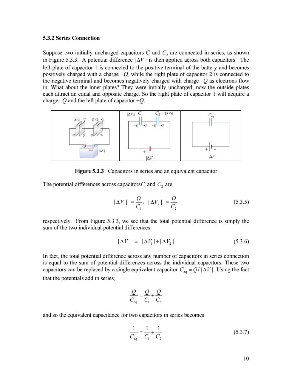
5.3.2 Series Connection Suppose two initially uncharged capacitors C1 and C2 are connected in series, as shown in Figure 5.3.3. A potential difference | ∆V | is then applied across both capacitors. The left plate of capacitor 1 is connected to the positive terminal of the battery and becomes positively charged with a charge +Q, while the right plate of capacitor 2 is connected to the negative terminal and becomes negatively charged with charge –Q as electrons flow in. What about the inner plates? They were initially uncharged; now the outside plates each attract an equal and opposite charge. So the right plate of capacitor 1 will acquire a charge –Q and the left plate of capacitor +Q. Figure 5.3.3 Capacitors in series and an equivalent capacitor The potential differences across capacitorsC1 and C are 2 1 2 1 2 Q | V | , | V | C C ∆ = ∆ = Q 2 (5.3.5) respectively. From Figure 5.3.3, we see that the total potential difference is simply the sum of the two individual potential differences: 1 | V∆ | = ∆| V ||V + ∆ | (5.3.6) In fact, the total potential difference across any number of capacitors in series connection is equal to the sum of potential differences across the individual capacitors. These two capacitors can be replaced by a single equivalent capacitor eq C Q= / | ∆V |. Using the fact that the potentials add in series, eq 1 2 Q Q Q C C C = + and so the equivalent capacitance for two capacitors in series becomes eq 1 2 1 1 1 C C C = + (5.3.7) 10
The generalization to any number of capacitors connected in series is 11 1 十十 1=1 (series (5.3.8) Example 5.4:Equivalent Capacitance Find the equivalent capacitance for the combination of capacitors shown in Figure 5.3.4(a) Figure 5.3.4 (a)Capacitors connected in series and in parallel Solution: Since C and C2 are connected in parallel,their equivalent capacitance C12 is given by CI2=C]+C2 lrI C23 =C3 Figure 5.3.4(b)and (c)Equivalent circuits Now capacitor C12 is in series with C3,as seen from Figure 5.3.4(b).So,the equivalent capacitance C123 is given by 111 C123 C12 C3 or Ci2C:_(C+C2)C; C2+C3C1+C2+C3 11
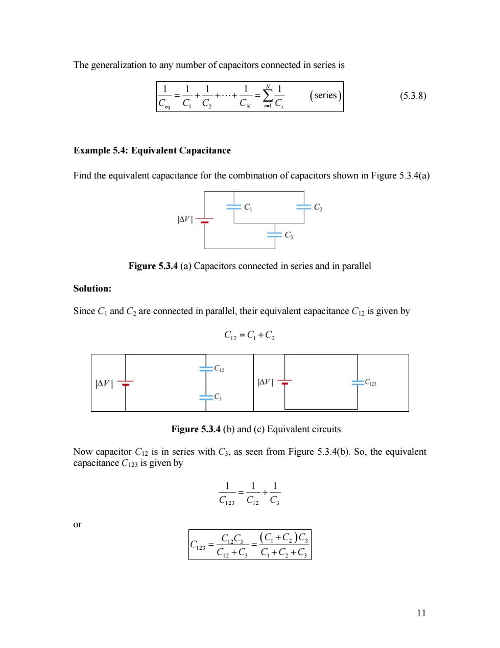
The generalization to any number of capacitors connected in series is ( eq 1 2 1 1 1 1 1 1 series N C C C CN i i= C = + +"+ = ∑ ) (5.3.8) Example 5.4: Equivalent Capacitance Find the equivalent capacitance for the combination of capacitors shown in Figure 5.3.4(a) Figure 5.3.4 (a) Capacitors connected in series and in parallel Solution: Since C1 and C2 are connected in parallel, their equivalent capacitance C12 is given by C C 12 = 1 +C2 Figure 5.3.4 (b) and (c) Equivalent circuits. Now capacitor C12 is in series with C3, as seen from Figure 5.3.4(b). So, the equivalent capacitance C123 is given by 123 12 3 1 1 C C C = + 1 or ( 1 2 ) 12 3 123 12 3 1 2 3 C C C C C C C C C C C + = = + + + 3 11
5.4 Storing Energy in a Capacitor As discussed in the introduction,capacitors can be used to stored electrical energy.The amount of energy stored is equal to the work done to charge it.During the charging process,the battery does work to remove charges from one plate and deposit them onto the other. ++++ Figure 5.4.1 Work is done by an external agent in bringing +dg from the negative plate and depositing the charge on the positive plate. Let the capacitor be initially uncharged.In each plate of the capacitor,there are many negative and positive charges,but the number of negative charges balances the number of positive charges,so that there is no net charge,and therefore no electric field between the plates.We have a magic bucket and a set of stairs from the bottom plate to the top plate (Figure 5.4.1). We start out at the bottom plate,fill our magic bucket with a charge +dg,carry the bucket up the stairs and dump the contents of the bucket on the top plate,charging it up positive to charge +dg.However,in doing so,the bottom plate is now charged to -dg. Having emptied the bucket of charge,we now descend the stairs,get another bucketful of charge +dg,go back up the stairs and dump that charge on the top plate.We then repeat this process over and over.In this way we build up charge on the capacitor,and create electric field where there was none initially. Suppose the amount of charge on the top plate at some instant is +q,and the potential difference between the two plates is AV=g/C.To dump another bucket of charge +dg on the top plate,the amount of work done to overcome electrical repulsion is dw=AVIdg.If at the end of the charging process,the charge on the top plate is + then the total amount of work done in this process is w-4ar=是=是 (5.4.1) This is equal to the electrical potential energy Uof the system: g-5e1ac1av (5.4.2) 12
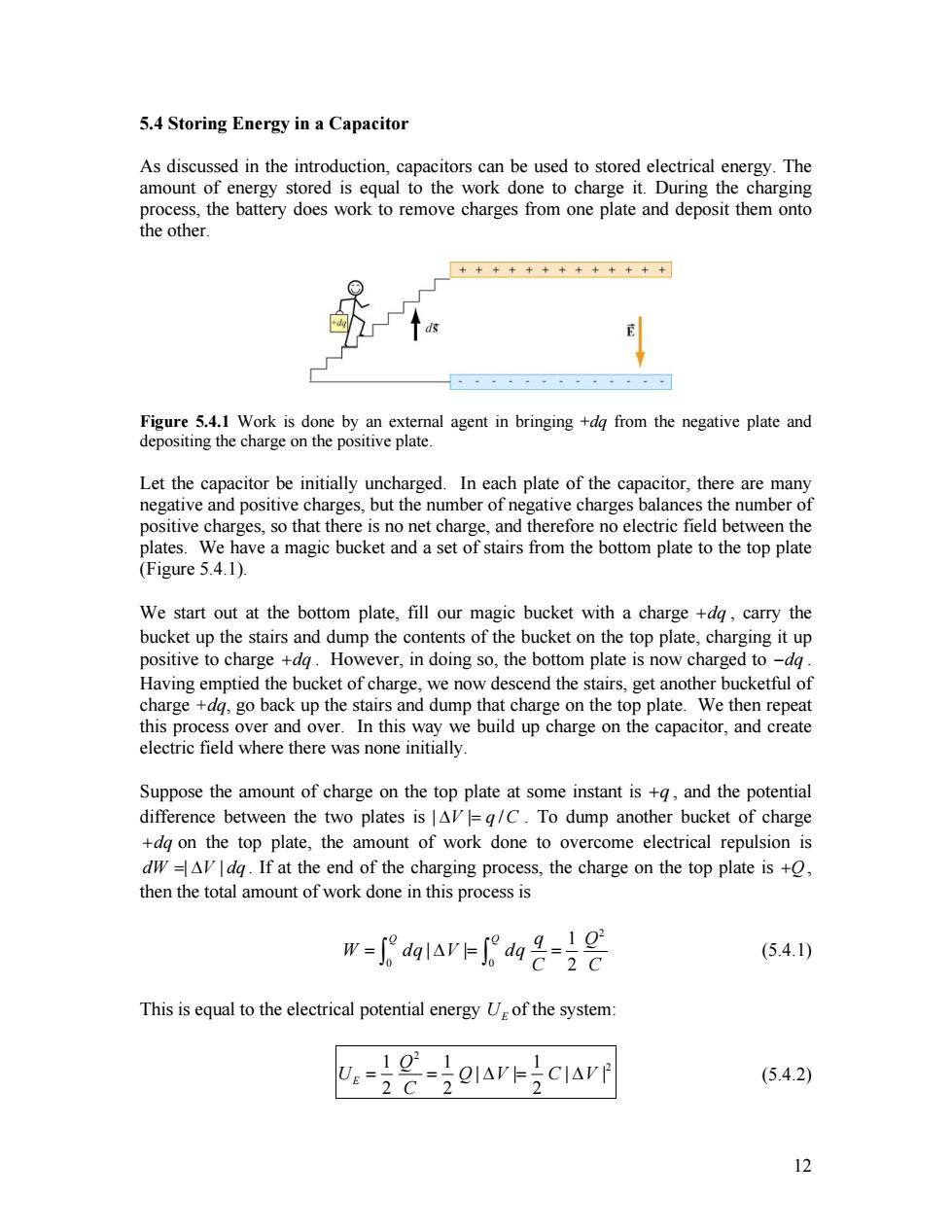
5.4 Storing Energy in a Capacitor As discussed in the introduction, capacitors can be used to stored electrical energy. The amount of energy stored is equal to the work done to charge it. During the charging process, the battery does work to remove charges from one plate and deposit them onto the other. Figure 5.4.1 Work is done by an external agent in bringing +dq from the negative plate and depositing the charge on the positive plate. Let the capacitor be initially uncharged. In each plate of the capacitor, there are many negative and positive charges, but the number of negative charges balances the number of positive charges, so that there is no net charge, and therefore no electric field between the plates. We have a magic bucket and a set of stairs from the bottom plate to the top plate (Figure 5.4.1). We start out at the bottom plate, fill our magic bucket with a charge , carry the bucket up the stairs and dump the contents of the bucket on the top plate, charging it up positive to charge . However, in doing so, the bottom plate is now charged to +dq +dq −dq . Having emptied the bucket of charge, we now descend the stairs, get another bucketful of charge +dq, go back up the stairs and dump that charge on the top plate. We then repeat this process over and over. In this way we build up charge on the capacitor, and create electric field where there was none initially. Suppose the amount of charge on the top plate at some instant is +q , and the potential difference between the two plates is | | ∆V q = /C . To dump another bucket of charge on the top plate, the amount of work done to overcome electrical repulsion is . If at the end of the charging process, the charge on the top plate is +dq dW = ∆| V | dq +Q , then the total amount of work done in this process is 2 0 0 1 | | 2 Q Q q Q W dq V dq C C = ∆ = = ∫ ∫ (5.4.1) This is equal to the electrical potential energy of the system: UE 2 1 1 1 2 | | | 2 2 2 E Q U Q V C C = = ∆ = ∆V | (5.4.2) 12
5.4.1 Energy Density of the Electric Field One can think of the energy stored in the capacitor as being stored in the electric field itself.In the case of a parallel-plate capacitor,with C=5A/d and AV=Ed,we have V-CIAVF (Ed (Ad) (5.4.3) 2 d Since the quantity Ad represents the volume between the plates,we can define the electric energy density as UE 1 4E= (5.4.4) Volume Note that ug is proportional to the square of the electric field.Alternatively,one may obtain the energy stored in the capacitor from the point of view of external work.Since the plates are oppositely charged,force must be applied to maintain a constant separation between them.From Eq.(4.4.7),we see that a small patch of charge Ag=(AA)experiences an attractive force AF=2(AA)/28.If the total area of the plate is A,then an external agent must exert a force F=/26 to pull the two plates apart.Since the electric field strength in the region between the plates is given by E=o/5o,the external force can be rewritten as Fo =502A (5.4.5) 2 Note that F is independent of d.The total amount of work done externally to separate the plates by a distance d is then Wom=∫fnds=fnd= (5.4.6) (2 consistent with Eq.(5.4.3).Since the potential energy of the system is equal to the work done by the external agent,we haveu=W/Ad=E2/2.In addition,we note that the expression for u is identical to Eq.(4.4.8)in Chapter 4.Therefore,the electric energy density ue can also be interpreted as electrostatic pressure P. Interactive Simulation 5.2:Charge Placed between Capacitor Plates This applet shown in Figure 5.4.2 is a simulation of an experiment in which an aluminum sphere sitting on the bottom plate of a capacitor is lifted to the top plate by the electrostatic force generated as the capacitor is charged.We have placed a non- 13
5.4.1 Energy Density of the Electric Field One can think of the energy stored in the capacitor as being stored in the electric field itself. In the case of a parallel-plate capacitor, with 0 C = ε A/ d and | | ∆V = Ed , we have ( ) ( 2 2 0 0 1 1 1 | | 2 2 2 E A U C V Ed E Ad d ) ε 2 = ∆ = = ε (5.4.3) Since the quantity Ad represents the volume between the plates, we can define the electric energy density as 2 0 1 Volume 2 E E U u = = ε E (5.4.4) Note that is proportional to the square of the electric field. Alternatively, one may obtain the energy stored in the capacitor from the point of view of external work. Since the plates are oppositely charged, force must be applied to maintain a constant separation between them. From Eq. (4.4.7), we see that a small patch of charge E u ∆ = q σ (∆A) experiences an attractive force 2 0 ∆ = F σ ( ) ∆A / 2ε . If the total area of the plate is A, then an external agent must exert a force 2 ext 0 F = σ A/ 2ε to pull the two plates apart. Since the electric field strength in the region between the plates is given by 0 E =σ / ε , the external force can be rewritten as 0 2 ext 2 F E A ε = (5.4.5) Note that is independent of d . The total amount of work done externally to separate the plates by a distance d is then Fext 2 0 ext ext ext 2 E A W d F d ⎛ ⎞ ε = ⋅ = = ⎜ ⎝ ⎠ ∫ F s ⎟ d G G (5.4.6) consistent with Eq. (5.4.3). Since the potential energy of the system is equal to the work done by the external agent, we have . In addition, we note that the expression for is identical to Eq. (4.4.8) in Chapter 4. Therefore, the electric energy density can also be interpreted as electrostatic pressure P. 2 ext 0 / E u W= Ad = ε E / 2 E u E u Interactive Simulation 5.2: Charge Placed between Capacitor Plates This applet shown in Figure 5.4.2 is a simulation of an experiment in which an aluminum sphere sitting on the bottom plate of a capacitor is lifted to the top plate by the electrostatic force generated as the capacitor is charged. We have placed a non- 13

conducting barrier just below the upper plate to prevent the sphere from touching it and discharging. Figure 5.4.2 Electrostatic force experienced by an aluminum sphere placed between the plates of a parallel-plate capacitor. While the sphere is in contact with the bottom plate,the charge density of the bottom of the sphere is the same as that of the lower plate.Thus,as the capacitor is charged,the charge density on the sphere increases proportional to the potential difference between the plates.In addition,energy flows in to the region between the plates as the electric field builds up.This can be seen in the motion of the electric field lines as they move from the edge to the center of the capacitor. As the potential difference between the plates increases,the sphere feels an increasing attraction towards the top plate,indicated by the increasing tension in the field as more field lines "attach"to it.Eventually this tension is enough to overcome the downward force of gravity,and the sphere is lifted.Once separated from the lower plate,the sphere charge density no longer increases,and it feels both an attractive force towards the upper plate(whose charge is roughly opposite that of the sphere)and a repulsive force from the lower one (whose charge is roughly equal to that of the sphere).The result is a net force upwards. Example 5.5:Electric Energy Density of Dry Air The breakdown field strength at which dry air loses its insulating ability and allows a discharge to pass through is E,=3x10 V/m.At this field strength,the electric energy density is: 4:=7E-(885x10cN:m203x10Vimj=40Ja 1 (5.4.7) Example 5.6:Energy Stored in a Spherical Shell Find the energy stored in a metallic spherical shell of radius a and charge O Solution: 14
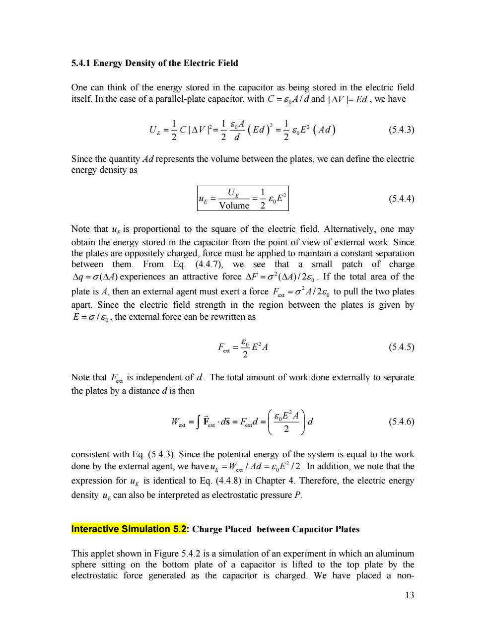
conducting barrier just below the upper plate to prevent the sphere from touching it and discharging. Figure 5.4.2 Electrostatic force experienced by an aluminum sphere placed between the plates of a parallel-plate capacitor. While the sphere is in contact with the bottom plate, the charge density of the bottom of the sphere is the same as that of the lower plate. Thus, as the capacitor is charged, the charge density on the sphere increases proportional to the potential difference between the plates. In addition, energy flows in to the region between the plates as the electric field builds up. This can be seen in the motion of the electric field lines as they move from the edge to the center of the capacitor. As the potential difference between the plates increases, the sphere feels an increasing attraction towards the top plate, indicated by the increasing tension in the field as more field lines "attach" to it. Eventually this tension is enough to overcome the downward force of gravity, and the sphere is lifted. Once separated from the lower plate, the sphere charge density no longer increases, and it feels both an attractive force towards the upper plate (whose charge is roughly opposite that of the sphere) and a repulsive force from the lower one (whose charge is roughly equal to that of the sphere). The result is a net force upwards. Example 5.5: Electric Energy Density of Dry Air The breakdown field strength at which dry air loses its insulating ability and allows a discharge to pass through is . At this field strength, the electric energy density is: 6 Eb = ×3 10 V/m ( )( ) 2 2 12 2 2 6 0 1 1 8 85 10 C /N m 3 10 V/m 40 J/m 2 2 E u E ε . − = = × ⋅ × = 3 (5.4.7) Example 5.6: Energy Stored in a Spherical Shell Find the energy stored in a metallic spherical shell of radius a and charge Q. Solution: 14