Chapter 11 Inductance and Magnetic Energy 11.1 Mutual Inductance........... 11-3 Example 11.1 Mutual Inductance of Two Concentric Co-planar Loops...............11-5 11.2 Self-Inductance.. 11-6 Example 11.2 Self-Inductance ofa Solenoid..11-6 Example 11.3 Self-Inductance of a Toroid.............. …11-7 Example 11.4 Mutual Inductance of a Coil Wrapped Around a Solenoid .11-9 11.3 Energy Stored in Magnetic Fields... .11-10 Example 11.5 Energy Stored in a Solenoid.......... 11-11 11.3.1 Creating and Destroying Magnetic Energy Animation 11-12 11.4 RL Circuits… 11-13 11.4.1 Self-Inductance and the Faraday's Law. 11-13 11.4.2 Kirchhoff's Loop Rule Modified for Inductors:a Warning 11-17 11.4.3 Example Voltmeter Readings with Time Changing Magnetic Fields...11-18 11.5 How can the Electric Field in an Inductor be Zero?... 11-21 11.6 Modified Kirchoffs Law (Misleading,see Section 11.4.2).................. 11-25 11.6.1 Rising Current............. .11-27 11.6.2 Decaying Current.... 11-29 11.7 LC Oscillations........... 11-30 11.8 The RLC Series Circuit.................. 11-34 11.9 Summary. 11-37 11.10 Appendix 1:General Solutions for the RLC Series Circuit. 11-39 11.10.1 Quality Factor.......... 11-41 11.11 Appendix 2:Stresses Transmitted by Magnetic Fields. 11-43 11.12 Problem-Solving Strategies....... 11-44 11.12.1 Calculating Self-Inductance.................. 11-44 11.12.2 Circuits containing inductors 。 11-45 11.13 Solved Problems................... 11-45 11.13.1 Energy stored in a toroid............. 11-45 11.13.2 Magnetic Energy Density 11-46 11.13.3 Mutual Inductance...... 11-47 11-1
11-1 Chapter 11 Inductance and Magnetic Energy 11.1 Mutual Inductance ........................................................................................... 11-3 Example 11.1 Mutual Inductance of Two Concentric Co-planar Loops............... 11-5 11.2 Self-Inductance ................................................................................................ 11-6 Example 11.2 Self-Inductance of a Solenoid......................................................... 11-6 Example 11.3 Self-Inductance of a Toroid............................................................ 11-7 Example 11.4 Mutual Inductance of a Coil Wrapped Around a Solenoid ............ 11-9 11.3 Energy Stored in Magnetic Fields.................................................................. 11-10 Example 11.5 Energy Stored in a Solenoid ......................................................... 11-11 11.3.1 Creating and Destroying Magnetic Energy Animation ......................... 11-12 11.4 RL Circuits..................................................................................................... 11-13 11.4.1 Self-Inductance and the Faraday’s Law................................................. 11-13 11.4.2 Kirchhoff's Loop Rule Modified for Inductors: a Warning................... 11-17 11.4.3 Example Voltmeter Readings with Time Changing Magnetic Fields... 11-18 11.5 How can the Electric Field in an Inductor be Zero? ...................................... 11-21 11.6 Modified Kirchoff’s Law (Misleading, see Section 11.4.2).......................... 11-25 11.6.1 Rising Current........................................................................................ 11-27 11.6.2 Decaying Current................................................................................... 11-29 11.7 LC Oscillations .............................................................................................. 11-30 11.8 The RLC Series Circuit .................................................................................. 11-34 11.9 Summary........................................................................................................ 11-37 11.10 Appendix 1: General Solutions for the RLC Series Circuit ........................... 11-39 11.10.1 Quality Factor ........................................................................................ 11-41 11.11 Appendix 2: Stresses Transmitted by Magnetic Fields.................................. 11-43 11.12 Problem-Solving Strategies ........................................................................... 11-44 11.12.1 Calculating Self-Inductance................................................................... 11-44 11.12.2 Circuits containing inductors................................................................. 11-45 11.13 Solved Problems ............................................................................................ 11-45 11.13.1 Energy stored in a toroid........................................................................ 11-45 11.13.2 Magnetic Energy Density ...................................................................... 11-46 11.13.3 Mutual Inductance ................................................................................. 11-47
11.13.4 RL Circuit.… 11-48 11.13.5 RL Circuit.11-50 11.13.6 LC Circuit......... 11-52 11.14 Conceptual Questions................. 11-53 11.15 Additional Problems.................... 11-54 11.15.1 Solenoid...... 11-54 11.15.2 Self-Inductance... 11-54 11.15.3 Coupled Inductors... 11-54 11.15.4 RL Circuit. 11-55 11.15.5 RL Circuit........... 11-56 11.15.6 Inductance of a Solenoid With and Without Iron Core.........................11-56 11.15.7 RLC Circuit.. 11-57 11.15.8 Spinning Cylinder 11-58 11.15.9 Spinning Loop... 11-59 11.15.10 LC Circuit… 11-59 11-2
11-2 11.13.4 RL Circuit............................................................................................... 11-48 11.13.5 RL Circuit............................................................................................... 11-50 11.13.6 LC Circuit .............................................................................................. 11-52 11.14 Conceptual Questions .................................................................................... 11-53 11.15 Additional Problems ...................................................................................... 11-54 11.15.1 Solenoid ................................................................................................. 11-54 11.15.2 Self-Inductance ...................................................................................... 11-54 11.15.3 Coupled Inductors.................................................................................. 11-54 11.15.4 RL Circuit............................................................................................... 11-55 11.15.5 RL Circuit............................................................................................... 11-56 11.15.6 Inductance of a Solenoid With and Without Iron Core ......................... 11-56 11.15.7 RLC Circuit............................................................................................ 11-57 11.15.8 Spinning Cylinder.................................................................................. 11-58 11.15.9 Spinning Loop........................................................................................ 11-59 11.15.10 LC Circuit .......................................................................................... 11-59
Inductance and Magnetic Energy 11.1 Mutual Inductance Suppose two coils are placed near each other,as shown in Figure 11.1.1 Coil2 N,Φ12 Coil 1 Figure 11.1.1 Changing current in coil 1 produces changing magnetic flux in coil 2. The first coil has N turns and carries a current I which gives rise to a magnetic field B.The second coil has N,turns.Because the two coils are close to each other,some of the magnetic field lines through coil 1 will also pass through coil 2.Let denote the magnetic flux through one turn of coil 2 due toI.Now,by varying I with time,there will be an induced emf associated with the changing magnetic flux in the second coil: -水9 (11.1.1) coil 2 The time rate of change of magnetic flux in coil 2 is proportional to the time rate of change of the current in coil 1: d④2=Mnd N2 dt i (11.1.2) where the proportionality constant M is called the mutual inductance.It can also be written as N2Φ2 M2= (11.1.3) 11-3
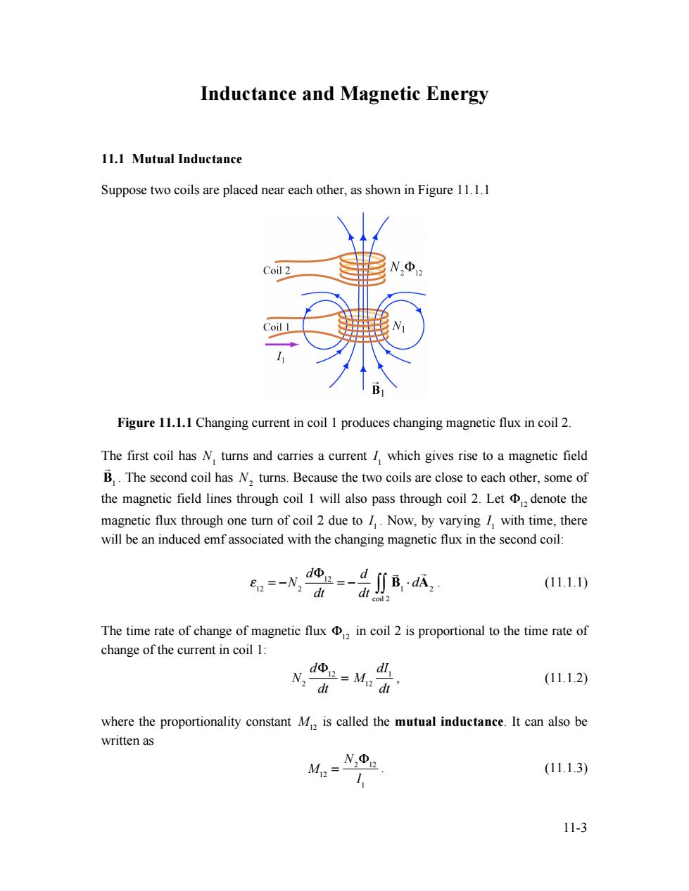
11-3 Inductance and Magnetic Energy 11.1 Mutual Inductance Suppose two coils are placed near each other, as shown in Figure 11.1.1 Figure 11.1.1 Changing current in coil 1 produces changing magnetic flux in coil 2. The first coil has N1 turns and carries a current I 1 which gives rise to a magnetic field ! B1 . The second coil has N2 turns. Because the two coils are close to each other, some of the magnetic field lines through coil 1 will also pass through coil 2. Let !12 denote the magnetic flux through one turn of coil 2 due to I 1 . Now, by varying I 1 with time, there will be an induced emf associated with the changing magnetic flux in the second coil: ! 12 = "N2 d#12 dt = " d dt ! B1 $ d ! A2 coil 2 %% . (11.1.1) The time rate of change of magnetic flux !12 in coil 2 is proportional to the time rate of change of the current in coil 1: N2 d!12 dt = M12 dI1 dt , (11.1.2) where the proportionality constant M12 is called the mutual inductance. It can also be written as M12 = N2 !12 I 1 . (11.1.3)
The SI unit for inductance is the henry [H]: 1 henry =1H=1T.m/A. (11.1.4) We shall see that the mutual inductance M,depends only on the geometrical properties of the two coils such as the number of turns and the radii of the two coils. In a similar manner,suppose instead there is a current 1,in the second coil and it is varying with time (Figure 11.1.2).Then the induced emf in coil 1 becomes d=-dfB,d瓜 =-N dt di (11.1.5) coil I and a current is induced in coil 1. B2 Coil2 Coil 1 NΦ2 Figure 11.1.2 Changing current in coil 2 produces changing magnetic flux in coil 1. This changing flux in coil I is proportional to the changing current in coil 2, d=Ma dt N、dt (11.1.6) where the proportionality constant M is another mutual inductance and can be written as NΦL M= (11.1.7) 12 The mutual inductance reciprocity theorem states that the constants are equal M2=M≡M. (111.8) 11-4
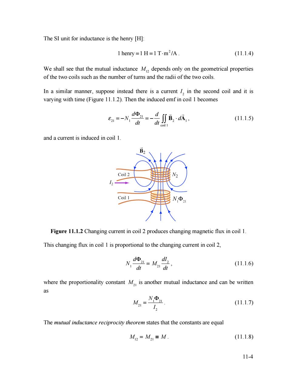
11-4 The SI unit for inductance is the henry [H]: 1 henry = 1 H = 1 T!m2 /A . (11.1.4) We shall see that the mutual inductance M12 depends only on the geometrical properties of the two coils such as the number of turns and the radii of the two coils. In a similar manner, suppose instead there is a current I2 in the second coil and it is varying with time (Figure 11.1.2). Then the induced emf in coil 1 becomes ! 21 = "N1 d#21 dt = " d dt ! B2 $ d ! A1 coil 1 %% , (11.1.5) and a current is induced in coil 1. Figure 11.1.2 Changing current in coil 2 produces changing magnetic flux in coil 1. This changing flux in coil 1 is proportional to the changing current in coil 2, N1 d!21 dt = M21 dI2 dt , (11.1.6) where the proportionality constant M21 is another mutual inductance and can be written as M21 = N1 !21 I2 . (11.1.7) The mutual inductance reciprocity theorem states that the constants are equal M12 = M21 ! M . (11.1.8)
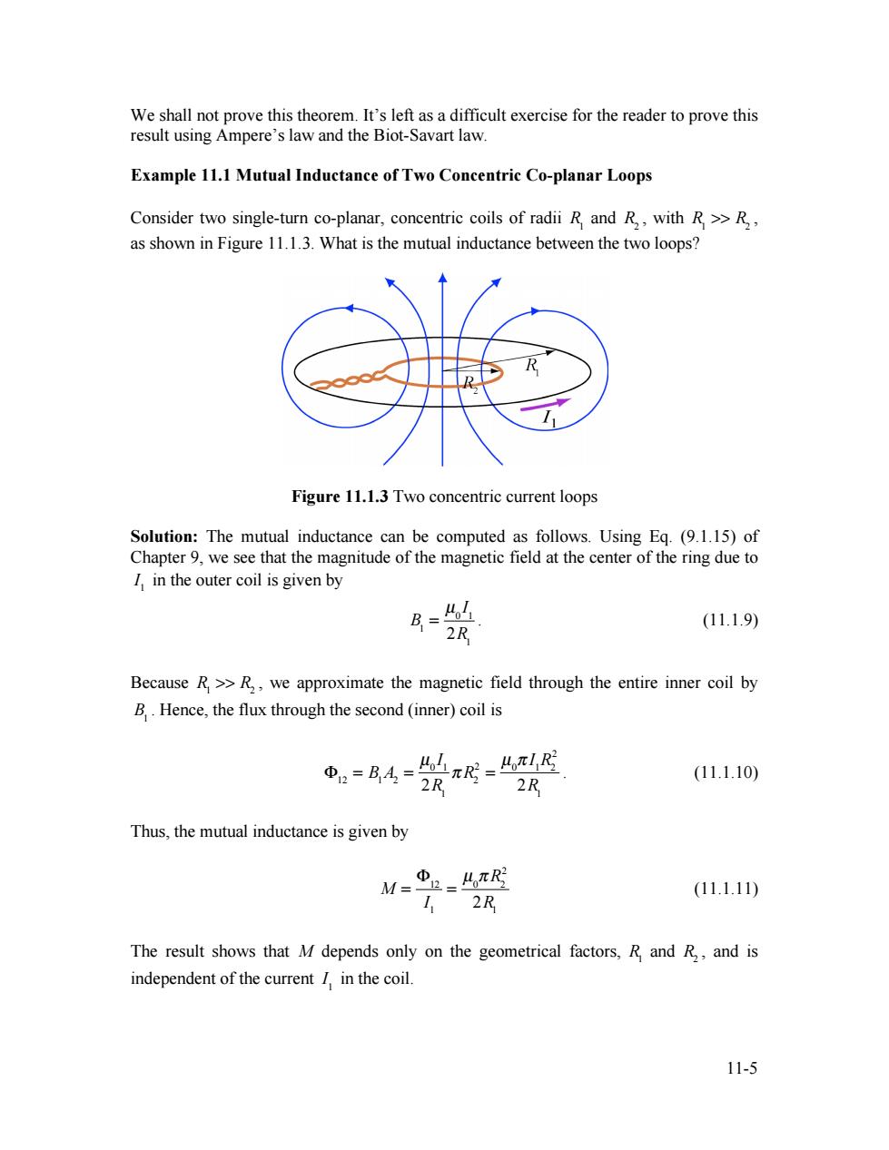
We shall not prove this theorem.It's left as a difficult exercise for the reader to prove this result using Ampere's law and the Biot-Savart law. Example 11.1 Mutual Inductance of Two Concentric Co-planar Loops Consider two single-turn co-planar,concentric coils of radii R and R,,with R>>R, as shown in Figure 11.1.3.What is the mutual inductance between the two loops? Figure 11.1.3 Two concentric current loops Solution:The mutual inductance can be computed as follows.Using Eq.(9.1.15)of Chapter 9,we see that the magnitude of the magnetic field at the center of the ring due to I in the outer coil is given by B= Lo (11.1.9) 2R Because R>>R,,we approximate the magnetic field through the entire inner coil by B.Hence,the flux through the second (inner)coil is =B4=π=LR 2R (11.1.10) 2R Thus,the mutual inductance is given by M= 2=4π及 11.1.11) 112R The result shows that M depends only on the geometrical factors,R and R,and is independent of the current I,in the coil. 11-5
11-5 We shall not prove this theorem. It’s left as a difficult exercise for the reader to prove this result using Ampere’s law and the Biot-Savart law. Example 11.1 Mutual Inductance of Two Concentric Co-planar Loops Consider two single-turn co-planar, concentric coils of radii R1 and R2 , with R1 >> R2 , as shown in Figure 11.1.3. What is the mutual inductance between the two loops? Figure 11.1.3 Two concentric current loops Solution: The mutual inductance can be computed as follows. Using Eq. (9.1.15) of Chapter 9, we see that the magnitude of the magnetic field at the center of the ring due to I 1 in the outer coil is given by B1 = µ0 I 1 2R1 . (11.1.9) Because R1 >> R2 , we approximate the magnetic field through the entire inner coil by B1 . Hence, the flux through the second (inner) coil is !12 = B1A2 = µ0 I 1 2R1 " R2 2 = µ0 " I 1R2 2 2R1 . (11.1.10) Thus, the mutual inductance is given by M = !12 I 1 = µ0 " R2 2 2R1 (11.1.11) The result shows that M depends only on the geometrical factors, R1 and R2 , and is independent of the current I 1 in the coil