Chapter 7 DC Circuits 7.1 Introduction. 7-3 Example 7.1.1:Junctions,branches and loops 7-4 7.2 Electromotive Force..... 7-5 7.3 Electrical Energy and Power........ 7-9 7.4 Resistors in Series and in Parallel. .7-10 7.5 Kirchhoff's Circuit Rules................ .7-12 7.6 Voltage-Current Measurements..... .7-14 7.7 Capacitors in Electric Circuits .7-15 7.7.1 Parallel Connection ..7-16 7.7.2 Series Connection.......... .7-17 Example 7.7.1:Equivalent Capacitance... .7-19 Example 7.7.2:Capacitance with Dielectrics 7-19 7.8 RC Circuit… 7-20 7.8.1 Charging a Capacitor. .7-20 7.8.2 Discharging a Capacitor.7-24 7.9 Summary. 。。 7-26 7.10 Problem-Solving Strategy:Applying Kirchhoffs Rules..................7.-27 7.11 Solved Problems… 7-31 7.11.1 Equivalent Resistance................. .7-31 7.11.2 Variable Resistance................ .7-32 7.11.3 RCCircuit.. .7-33 7.11.4 Parallel vs.Series Connections .7-34 7.11.5 Resistor Network........ 7-36 7.11.6 Equivalent Capacitance 7-37 7.12 Conceptual Questions 7-38 7.13 Additional Problems.... 7-39 7-1
7-1 Chapter 7 DC Circuits 7.1 Introduction.......................................................................................................... 7-3 Example 7.1.1: Junctions, branches and loops ........................................................ 7-4 7.2 Electromotive Force............................................................................................. 7-5 7.3 Electrical Energy and Power................................................................................ 7-9 7.4 Resistors in Series and in Parallel...................................................................... 7-10 7.5 Kirchhoff’s Circuit Rules................................................................................... 7-12 7.6 Voltage-Current Measurements......................................................................... 7-14 7.7 Capacitors in Electric Circuits........................................................................... 7-15 7.7.1 Parallel Connection .................................................................................... 7-16 7.7.2 Series Connection....................................................................................... 7-17 Example 7.7.1: Equivalent Capacitance ................................................................ 7-19 Example 7.7.2: Capacitance with Dielectrics........................................................ 7-19 7.8 RC Circuit.......................................................................................................... 7-20 7.8.1 Charging a Capacitor.................................................................................. 7-20 7.8.2 Discharging a Capacitor............................................................................. 7-24 7.9 Summary............................................................................................................ 7-26 7.10 Problem-Solving Strategy: Applying Kirchhoff’s Rules................................... 7-27 7.11 Solved Problems................................................................................................ 7-31 7.11.1 Equivalent Resistance................................................................................. 7-31 7.11.2 Variable Resistance .................................................................................... 7-32 7.11.3 RC Circuit................................................................................................... 7-33 7.11.4 Parallel vs. Series Connections .................................................................. 7-34 7.11.5 Resistor Network........................................................................................ 7-36 7.11.6 Equivalent Capacitance .............................................................................. 7-37 7.12 Conceptual Questions ........................................................................................ 7-38 7.13 Additional Problems.......................................................................................... 7-39
7.13.1 Resistive Circuits. 7-39 7.13.2 Multi-loop Circuit .7-39 7.13.3 Power Delivered to the Resistors. 7-40 7.13.4 Resistor Network........... 7-40 7.13.5 RC Circuit.............. .7-40 7.13.6 Resistors in Series and Parallel..... 7-41 7.13.7 Capacitors in Series and in Parallel 7-41 7.13.8 Power Loss and Ohm's Law .................. .7-42 7.13.9 Power,Current,and Potential difference .7-42 7-2
7-2 7.13.1 Resistive Circuits........................................................................................ 7-39 7.13.2 Multi-loop Circuit....................................................................................... 7-39 7.13.3 Power Delivered to the Resistors ............................................................... 7-40 7.13.4 Resistor Network........................................................................................ 7-40 7.13.5 RC Circuit................................................................................................... 7-40 7.13.6 Resistors in Series and Parallel .................................................................. 7-41 7.13.7 Capacitors in Series and in Parallel............................................................ 7-41 7.13.8 Power Loss and Ohm’s Law ...................................................................... 7-42 7.13.9 Power, Current, and Potential difference ................................................... 7-42
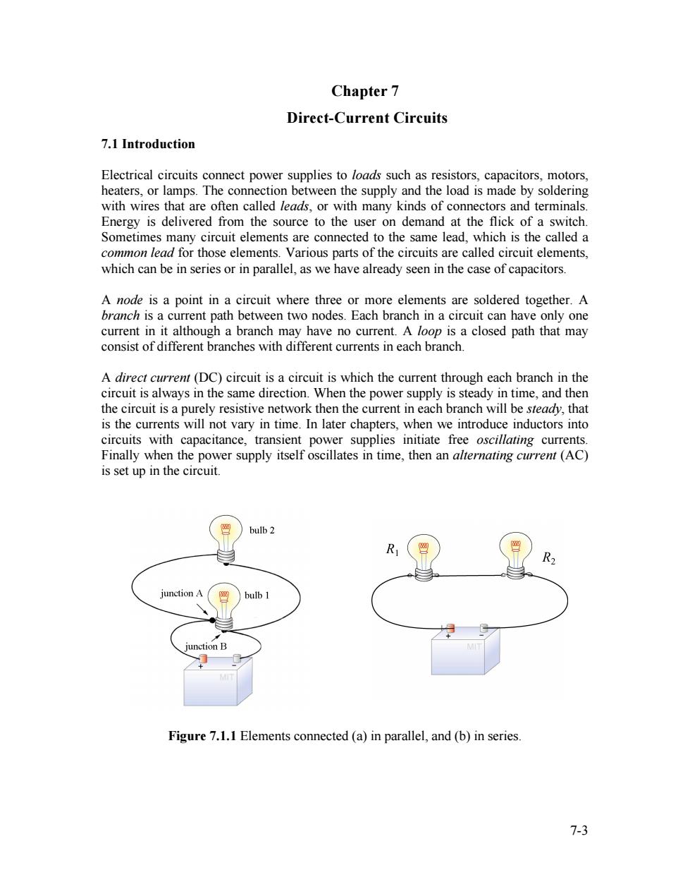
Chapter 7 Direct-Current Circuits 7.1 Introduction Electrical circuits connect power supplies to loads such as resistors,capacitors,motors, heaters,or lamps.The connection between the supply and the load is made by soldering with wires that are often called leads,or with many kinds of connectors and terminals. Energy is delivered from the source to the user on demand at the flick of a switch Sometimes many circuit elements are connected to the same lead,which is the called a common lead for those elements.Various parts of the circuits are called circuit elements, which can be in series or in parallel,as we have already seen in the case of capacitors. A node is a point in a circuit where three or more elements are soldered together.A branch is a current path between two nodes.Each branch in a circuit can have only one current in it although a branch may have no current.A loop is a closed path that may consist of different branches with different currents in each branch. A direct current (DC)circuit is a circuit is which the current through each branch in the circuit is always in the same direction.When the power supply is steady in time,and then the circuit is a purely resistive network then the current in each branch will be steady,that is the currents will not vary in time.In later chapters,when we introduce inductors into circuits with capacitance,transient power supplies initiate free oscillating currents. Finally when the power supply itself oscillates in time,then an alternating current(AC) is set up in the circuit. bulb 2 R2 junction A bulb 1 Junction B Figure 7.1.1 Elements connected (a)in parallel,and (b)in series. 7-3
7-3 Chapter 7 Direct-Current Circuits 7.1 Introduction Electrical circuits connect power supplies to loads such as resistors, capacitors, motors, heaters, or lamps. The connection between the supply and the load is made by soldering with wires that are often called leads, or with many kinds of connectors and terminals. Energy is delivered from the source to the user on demand at the flick of a switch. Sometimes many circuit elements are connected to the same lead, which is the called a common lead for those elements. Various parts of the circuits are called circuit elements, which can be in series or in parallel, as we have already seen in the case of capacitors. A node is a point in a circuit where three or more elements are soldered together. A branch is a current path between two nodes. Each branch in a circuit can have only one current in it although a branch may have no current. A loop is a closed path that may consist of different branches with different currents in each branch. A direct current (DC) circuit is a circuit is which the current through each branch in the circuit is always in the same direction. When the power supply is steady in time, and then the circuit is a purely resistive network then the current in each branch will be steady, that is the currents will not vary in time. In later chapters, when we introduce inductors into circuits with capacitance, transient power supplies initiate free oscillating currents. Finally when the power supply itself oscillates in time, then an alternating current (AC) is set up in the circuit. Figure 7.1.1 Elements connected (a) in parallel, and (b) in series
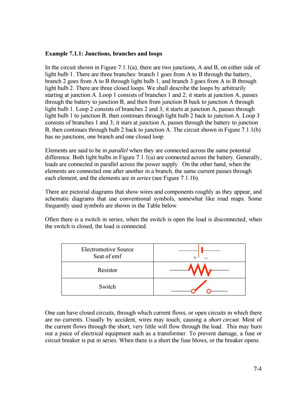
Example 7.1.1:Junctions,branches and loops In the circuit shown in Figure 7.1.1(a),there are two junctions,A and B,on either side of light bulb 1.There are three branches:branch 1 goes from A to B through the battery, branch 2 goes from A to B through light bulb 1,and branch 3 goes from A to B through light bulb 2.There are three closed loops.We shall describe the loops by arbitrarily starting at junction A.Loop 1 consists of branches 1 and 2;it starts at junction A,passes through the battery to junction B,and then from junction B back to junction A through light bulb 1.Loop 2 consists of branches 2 and 3;it starts at junction A,passes through light bulb I to junction B,then continues through light bulb 2 back to junction A.Loop 3 consists of branches 1 and 3;it stars at junction A,passes through the battery to junction B,then continues through bulb 2 back to junction A.The circuit shown in Figure 7.1.1(b) has no junctions,one branch and one closed loop. Elements are said to be in parallel when they are connected across the same potential difference.Both light bulbs in Figure 7.1.1(a)are connected across the battery.Generally, loads are connected in parallel across the power supply.On the other hand,when the elements are connected one after another in a branch,the same current passes through each element,and the elements are in series (see Figure 7.1.1b). There are pictorial diagrams that show wires and components roughly as they appear,and schematic diagrams that use conventional symbols,somewhat like road maps.Some frequently used symbols are shown in the Table below. Often there is a switch in series;when the switch is open the load is disconnected;when the switch is closed,the load is connected. Electromotive Source Seat of emf Resistor Switch One can have closed circuits,through which current flows,or open circuits in which there are no currents.Usually by accident,wires may touch,causing a short circuit.Most of the current flows through the short,very little will flow through the load.This may burn out a piece of electrical equipment such as a transformer.To prevent damage,a fuse or circuit breaker is put in series.When there is a short the fuse blows,or the breaker opens. 7-4
7-4 Example 7.1.1: Junctions, branches and loops In the circuit shown in Figure 7.1.1(a), there are two junctions, A and B, on either side of light bulb 1. There are three branches: branch 1 goes from A to B through the battery, branch 2 goes from A to B through light bulb 1, and branch 3 goes from A to B through light bulb 2. There are three closed loops. We shall describe the loops by arbitrarily starting at junction A. Loop 1 consists of branches 1 and 2; it starts at junction A, passes through the battery to junction B, and then from junction B back to junction A through light bulb 1. Loop 2 consists of branches 2 and 3; it starts at junction A, passes through light bulb 1 to junction B, then continues through light bulb 2 back to junction A. Loop 3 consists of branches 1 and 3; it stars at junction A, passes through the battery to junction B, then continues through bulb 2 back to junction A. The circuit shown in Figure 7.1.1(b) has no junctions, one branch and one closed loop. Elements are said to be in parallel when they are connected across the same potential difference. Both light bulbs in Figure 7.1.1(a) are connected across the battery. Generally, loads are connected in parallel across the power supply. On the other hand, when the elements are connected one after another in a branch, the same current passes through each element, and the elements are in series (see Figure 7.1.1b). There are pictorial diagrams that show wires and components roughly as they appear, and schematic diagrams that use conventional symbols, somewhat like road maps. Some frequently used symbols are shown in the Table below. Often there is a switch in series; when the switch is open the load is disconnected; when the switch is closed, the load is connected. Electromotive Source Seat of emf Resistor Switch One can have closed circuits, through which current flows, or open circuits in which there are no currents. Usually by accident, wires may touch, causing a short circuit. Most of the current flows through the short, very little will flow through the load. This may burn out a piece of electrical equipment such as a transformer. To prevent damage, a fuse or circuit breaker is put in series. When there is a short the fuse blows, or the breaker opens
In electrical circuits,a point(or some common lead)is chosen as the ground.This point is assigned an arbitrary voltage,usually zero,and the voltage Iat any point in the circuit is defined as the potential difference between that point and ground. 7.2 Electromotive Force Consider an electric circuit shown in Figure 7.2.1(a).To drive the current around the circuit,the battery undergoes a discharging process that converts chemical energy into electric energy that eventually gets dissipated as heat in the resistor. In the external circuit,the electrostatic field,E,is directed from the positive terminal of the battery to the negative terminal of the battery,exerting a force on the charges in the wire to produce a current from the positive to the negative terminal.The electrostatic field also insures that the current in the wire is uniform.Recall that the electrostatic field is a conservative vector field and so the line integral around the loop in Figure 7.2.1(b)is zero, ∫Es=0 (7.2.1) loop [E.ds=0 Figure 7.2.1(a)A simple circuit consisting of a battery and a resistor Figure 7.2.1(b)Integral of electrostatic field is zero around loop. Inside the battery,in the region close to the positive terminal,the electrostatic field points away from the positive terminal.In the region close to the negative terminal,the electrostatic field points towards the negative terminal.(In the region in between,the electrostatic field may point in either direction depending on the nature of the battery.) The current is directed from the negative to the positive terminals.Near both terminals, the electrostatic field points in the opposite direction of the current. In order to maintain the current,there must that be some force that transports charge carriers in the opposite direction in which the electrostatic field is trying to move them The origin of this source force,F,in batteries is a chemical force.In the regions near the terminal where chemical reactions are taking place,chemical forces move charge carriers in the opposite direction in which the electrostatic field is trying to move them.The work done per unit charge by this source force in moving a charge carrier with charge q from the negative to the positive terminal is given by the expression, 7-5
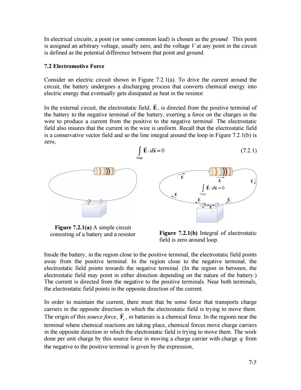
7-5 In electrical circuits, a point (or some common lead) is chosen as the ground. This point is assigned an arbitrary voltage, usually zero, and the voltage V at any point in the circuit is defined as the potential difference between that point and ground. 7.2 Electromotive Force Consider an electric circuit shown in Figure 7.2.1(a). To drive the current around the circuit, the battery undergoes a discharging process that converts chemical energy into electric energy that eventually gets dissipated as heat in the resistor. In the external circuit, the electrostatic field, E, is directed from the positive terminal of the battery to the negative terminal of the battery, exerting a force on the charges in the wire to produce a current from the positive to the negative terminal. The electrostatic field also insures that the current in the wire is uniform. Recall that the electrostatic field is a conservative vector field and so the line integral around the loop in Figure 7.2.1(b) is zero, E⋅d s = 0 loop ∫ (7.2.1) Figure 7.2.1(a) A simple circuit consisting of a battery and a resistor Figure 7.2.1(b) Integral of electrostatic field is zero around loop. Inside the battery, in the region close to the positive terminal, the electrostatic field points away from the positive terminal. In the region close to the negative terminal, the electrostatic field points towards the negative terminal. (In the region in between, the electrostatic field may point in either direction depending on the nature of the battery.) The current is directed from the negative to the positive terminals. Near both terminals, the electrostatic field points in the opposite direction of the current. In order to maintain the current, there must that be some force that transports charge carriers in the opposite direction in which the electrostatic field is trying to move them. The origin of this source force, Fs , in batteries is a chemical force. In the regions near the terminal where chemical reactions are taking place, chemical forces move charge carriers in the opposite direction in which the electrostatic field is trying to move them. The work done per unit charge by this source force in moving a charge carrier with charge q from the negative to the positive terminal is given by the expression