Chapter 5 Capacitance and Dielectrics 5.1 Introduction.. 5-3 5.2 Calculation of Capacitance................ 5-4 Example 5.1:Parallel-Plate Capacitor............ 5-4 Example 5.2:Cylindrical Capacitor 5-6 Example 5.3:Spherical Capacitor............... 5-7 5.3 Storing Energy in a Capacitor. 5-8 5.3.1 Energy Density of the Electric Field..... 5-10 Example 5.4:Electric Energy Density of Dry Air 5-11 Example 5.5:Energy Stored in a Spherical Shell 5-11 5.4 Dielectrics.. 5-12 5.4.1 Polarization............ 5-14 5.4.2 Dielectrics without Battery.............. 5-17 5.4.3 Dielectrics with Battery................ .5-18 5.4.4 Gauss's Law for Dielectrics.... 5-19 Example 5.6:Capacitance with Dielectrics..... 5-21 5.5 Creating Electric Fields................... 5-22 5.5.1 Creating an Electric Dipole Movie......... .5-22 5.5.2 Creating and Destroying Electric Energy Movie.................... .5-24 5-25 5.6 Summary.......….……….5- 5.7 Appendix:Electric Fields Hold Atoms Together.5-27 5.7.1 Ionic and van der Waals Forces.5-27 5.8 Problem-Solving Strategy:Calculating Capacitance...............5-29 5.9 Solved problems531 5.9.1 Capacitor Filled with Two Different Dielectrics......5.-31 5.9.2 Capacitor with Dielectrics................ .5-32 5.9.3 Capacitor Connected to a Spring................. 5-33 5.10 Conceptual Questions.................. 5-34 5.11 Additional Problems.................. 5-35 5.11.1 Capacitors and Dielectrics.............. 5-35 5-1
5-1 Chapter 5 Capacitance and Dielectrics 5.1 Introduction......................................................................................................... 5-3 5.2 Calculation of Capacitance ................................................................................. 5-4 Example 5.1: Parallel-Plate Capacitor..................................................................... 5-4 Example 5.2: Cylindrical Capacitor......................................................................... 5-6 Example 5.3: Spherical Capacitor............................................................................ 5-7 5.3 Storing Energy in a Capacitor............................................................................. 5-8 5.3.1 Energy Density of the Electric Field.......................................................... 5-10 Example 5.4: Electric Energy Density of Dry Air................................................. 5-11 Example 5.5: Energy Stored in a Spherical Shell.................................................. 5-11 5.4 Dielectrics......................................................................................................... 5-12 5.4.1 Polarization ................................................................................................ 5-14 5.4.2 Dielectrics without Battery ........................................................................ 5-17 5.4.3 Dielectrics with Battery ............................................................................. 5-18 5.4.4 Gauss’s Law for Dielectrics....................................................................... 5-19 Example 5.6: Capacitance with Dielectrics ........................................................... 5-21 5.5 Creating Electric Fields .................................................................................... 5-22 5.5.1 Creating an Electric Dipole Movie ............................................................ 5-22 5.5.2 Creating and Destroying Electric Energy Movie....................................... 5-24 5.6 Summary........................................................................................................... 5-25 5.7 Appendix: Electric Fields Hold Atoms Together ............................................. 5-27 5.7.1 Ionic and van der Waals Forces................................................................. 5-27 5.8 Problem-Solving Strategy: Calculating Capacitance........................................ 5-29 5.9 Solved Problems............................................................................................... 5-31 5.9.1 Capacitor Filled with Two Different Dielectrics....................................... 5-31 5.9.2 Capacitor with Dielectrics.......................................................................... 5-32 5.9.3 Capacitor Connected to a Spring ............................................................... 5-33 5.10 Conceptual Questions....................................................................................... 5-34 5.11 Additional Problems......................................................................................... 5-35 5.11.1 Capacitors and Dielectrics.......................................................................... 5-35
5.11.2 Gauss's Law in the Presence of a Dielectric...5-35 5.11.3 Gauss's Law and Dielectrics.5-36 5.11.4 A Capacitor with a Dielectric5-36 5.11.5 Force on the Plates of a Capacitor.... 5-37 5.11.6 Energy Density in a Capacitor with a Dielectric................................. 5-38 5-2
5-2 5.11.2 Gauss’s Law in the Presence of a Dielectric .............................................. 5-35 5.11.3 Gauss’s Law and Dielectrics...................................................................... 5-36 5.11.4 A Capacitor with a Dielectric..................................................................... 5-36 5.11.5 Force on the Plates of a Capacitor.............................................................. 5-37 5.11.6 Energy Density in a Capacitor with a Dielectric........................................ 5-38

Capacitance and Dielectrics 5.1 Introduction A capacitor is a device that stores electric charge.Capacitors vary in shape and size,but the basic configuration is two conductors carrying equal but opposite charges(Figure 5.1.1).Capacitors have many important applications in electronics.Some examples include storing electric potential energy,delaying voltage changes when coupled with resistors,filtering out unwanted frequency signals,forming resonant circuits and making frequency-dependent and independent voltage dividers when combined with resistors. Some of these applications will be discussed in latter chapters. Figure 5.1.1 Basic configuration of a capacitor. In the uncharged state,the charge on either one of the conductors in the capacitor is zero. During the charging process,a charge o is moved from one conductor to the other one, giving one conductor a charge,and the other one a charge -O.A potential difference Al is created,with the positively charged conductor at a higher potential than the negatively charged conductor.Note that whether charged or uncharged,the net charge on the capacitor as a whole is zero. The simplest example of a capacitor consists of two conducting plates of area A,which are parallel to each other,and separated by a distance d,as shown in Figure 5.1.2. Figure 5.1.2 A parallel-plate capacitor Experiments show that the amount of charge o stored in a capacitor is linearly proportional to Al,the electric potential difference between the plates.Thus,we may write 5-3
5-3 Capacitance and Dielectrics 5.1 Introduction A capacitor is a device that stores electric charge. Capacitors vary in shape and size, but the basic configuration is two conductors carrying equal but opposite charges (Figure 5.1.1). Capacitors have many important applications in electronics. Some examples include storing electric potential energy, delaying voltage changes when coupled with resistors, filtering out unwanted frequency signals, forming resonant circuits and making frequency-dependent and independent voltage dividers when combined with resistors. Some of these applications will be discussed in latter chapters. Figure 5.1.1 Basic configuration of a capacitor. In the uncharged state, the charge on either one of the conductors in the capacitor is zero. During the charging process, a charge Q is moved from one conductor to the other one, giving one conductor a charge, and the other one a charge !Q . A potential difference !V is created, with the positively charged conductor at a higher potential than the negatively charged conductor. Note that whether charged or uncharged, the net charge on the capacitor as a whole is zero. The simplest example of a capacitor consists of two conducting plates of area A, which are parallel to each other, and separated by a distance d, as shown in Figure 5.1.2. Figure 5.1.2 A parallel-plate capacitor Experiments show that the amount of charge Q stored in a capacitor is linearly proportional to !V , the electric potential difference between the plates. Thus, we may write
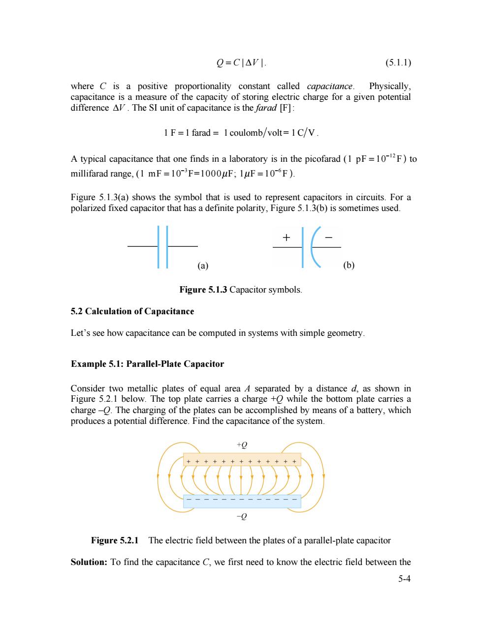
Q=CI△V|. (5.1.1) where C is a positive proportionality constant called capacitance.Physically. capacitance is a measure of the capacity of storing electric charge for a given potential difference AV.The SI unit of capacitance is the farad [F]: 1 F=1 farad 1 coulomb/volt=1C/V A typical capacitance that one finds in a laboratory is in the picofarad(1 pF=102F)to millifarad range,(1 mF=10-F=1000uF;1uF=10-F). Figure 5.1.3(a)shows the symbol that is used to represent capacitors in circuits.For a polarized fixed capacitor that has a definite polarity,Figure 5.1.3(b)is sometimes used. 。长 (a (b) Figure 5.1.3 Capacitor symbols. 5.2 Calculation of Capacitance Let's see how capacitance can be computed in systems with simple geometry. Example 5.1:Parallel-Plate Capacitor Consider two metallic plates of equal area 4 separated by a distance d,as shown in Figure 5.2.1 below.The top plate carries a charge +O while the bottom plate carries a charge-O.The charging of the plates can be accomplished by means of a battery,which produces a potential difference.Find the capacitance of the system. +0 Figure 5.2.1 The electric field between the plates of a parallel-plate capacitor Solution:To find the capacitance C,we first need to know the electric field between the 5-4
5-4 Q = C | !V |. (5.1.1) where C is a positive proportionality constant called capacitance. Physically, capacitance is a measure of the capacity of storing electric charge for a given potential difference !V . The SI unit of capacitance is the farad [F]: 1 F = 1 farad = 1 coulomb volt= 1C V . A typical capacitance that one finds in a laboratory is in the picofarad (1 pF = 10!12 F ) to millifarad range, (1 mF = 10!3 F=1000µF; 1µF = 10!6 F ). Figure 5.1.3(a) shows the symbol that is used to represent capacitors in circuits. For a polarized fixed capacitor that has a definite polarity, Figure 5.1.3(b) is sometimes used. (a) (b) Figure 5.1.3 Capacitor symbols. 5.2 Calculation of Capacitance Let’s see how capacitance can be computed in systems with simple geometry. Example 5.1: Parallel-Plate Capacitor Consider two metallic plates of equal area A separated by a distance d, as shown in Figure 5.2.1 below. The top plate carries a charge +Q while the bottom plate carries a charge –Q. The charging of the plates can be accomplished by means of a battery, which produces a potential difference. Find the capacitance of the system. Figure 5.2.1 The electric field between the plates of a parallel-plate capacitor Solution: To find the capacitance C, we first need to know the electric field between the
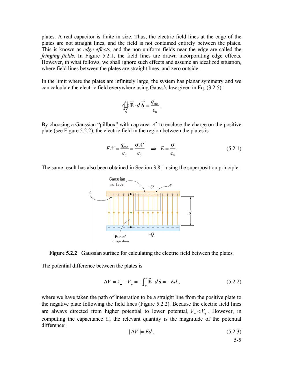
plates.A real capacitor is finite in size.Thus,the electric field lines at the edge of the plates are not straight lines,and the field is not contained entirely between the plates. This is known as edge effects,and the non-uniform fields near the edge are called the fringing fields.In Figure 5.2.1,the field lines are drawn incorporating edge effects However,in what follows,we shall ignore such effects and assume an idealized situation, where field lines between the plates are straight lines,and zero outside. In the limit where the plates are infinitely large,the system has planar symmetry and we can calculate the electric field everywhere using Gauss's law given in Eq.(3.2.5): ∯EdA=9 Eo By choosing a Gaussian "pillbox"with cap area A4'to enclose the charge on the positive plate (see Figure 5.2.2),the electric field in the region between the plates is EA'=9eE=A' (5.2.1) Eo →E= Eo The same result has also been obtained in Section 3.8.1 using the superposition principle. Gaussian surface +O -0 Path of intergration Figure 5.2.2 Gaussian surface for calculating the electric field between the plates. The potential difference between the plates is AV=V.-V,=-fE.ds=-Ed, (5.2.2) where we have taken the path of integration to be a straight line from the positive plate to the negative plate following the field lines(Figure 5.2.2).Because the electric field lines are always directed from higher potential to lower potential,V<V..However,in computing the capacitance C,the relevant quantity is the magnitude of the potential difference: l△V=Ed, (5.2.3) 5-5
5-5 plates. A real capacitor is finite in size. Thus, the electric field lines at the edge of the plates are not straight lines, and the field is not contained entirely between the plates. This is known as edge effects, and the non-uniform fields near the edge are called the fringing fields. In Figure 5.2.1, the field lines are drawn incorporating edge effects. However, in what follows, we shall ignore such effects and assume an idealized situation, where field lines between the plates are straight lines, and zero outside. In the limit where the plates are infinitely large, the system has planar symmetry and we can calculate the electric field everywhere using Gauss’s law given in Eq. (3.2.5): E !" ! d A !" S #"" = qenc # 0 . By choosing a Gaussian “pillbox” with cap area A! to enclose the charge on the positive plate (see Figure 5.2.2), the electric field in the region between the plates is EA' = qenc ! 0 = " A' ! 0 # E = " ! 0 . (5.2.1) The same result has also been obtained in Section 3.8.1 using the superposition principle. Figure 5.2.2 Gaussian surface for calculating the electric field between the plates. The potential difference between the plates is !V = V" "V+ = " ! E# d ! s + " $ = "Ed , (5.2.2) where we have taken the path of integration to be a straight line from the positive plate to the negative plate following the field lines (Figure 5.2.2). Because the electric field lines are always directed from higher potential to lower potential, V! <V+ . However, in computing the capacitance C, the relevant quantity is the magnitude of the potential difference: | !V |= Ed , (5.2.3)