Chapter I Introduction to Hydraulic and Pneumatic Transmission 1.3 Composing of Hydraulic Transmission System 1-Hydraulic pump 2-Adjustable throttle valve 3-Closed center directional valve 4-Hydraulic actuator 5-Working load 6-Relief valve 7-Filter 8-Reservoir (tank)-A container for storage Semi-structure sketch(visual) Symbol sketch (abstract) of liquid in a fluid power system. Figure.1-2 Principle of a typical hydraulic system Homepage List Upward达s Downwards Retumn Exit
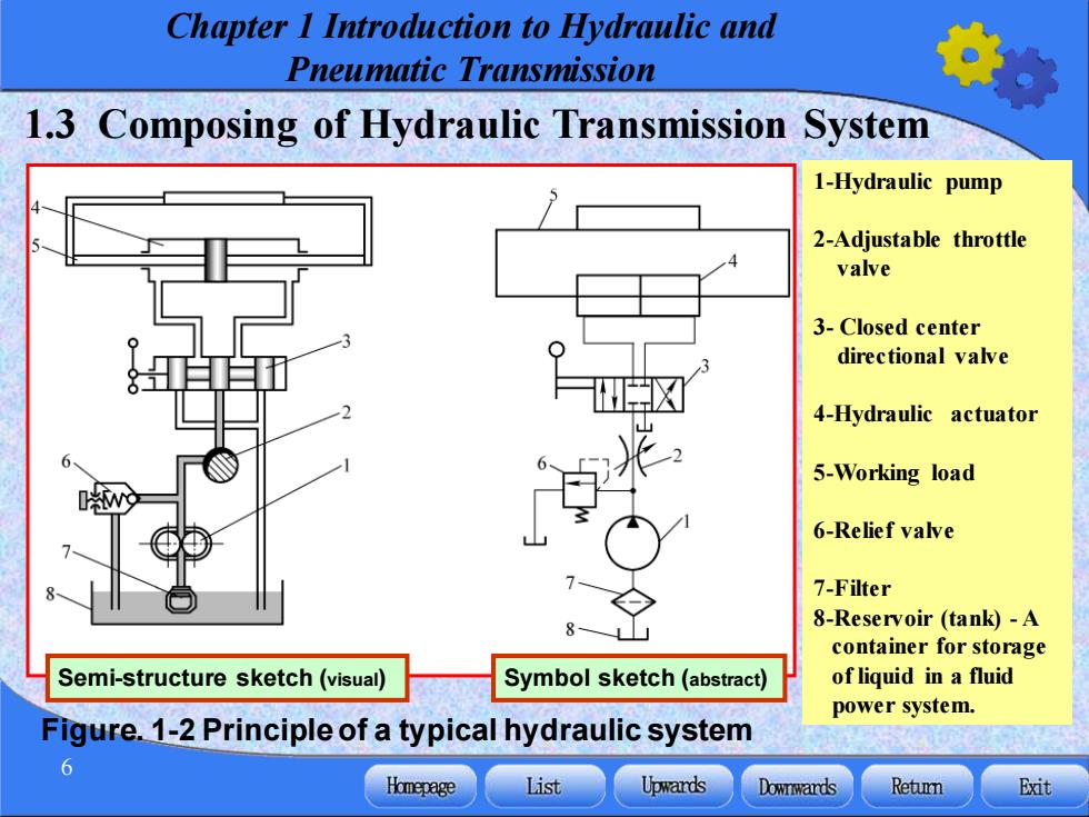
Chapter 1 Introduction to Hydraulic and Pneumatic Transmission 6 1.3 Composing of Hydraulic Transmission System Figure. 1-2 Principle of a typical hydraulic system 1-Hydraulic pump 2-Adjustable throttle valve 3- Closed center directional valve 4-Hydraulic actuator 5-Working load 6-Relief valve 7-Filter 8-Reservoir (tank) - A container for storage of liquid in a fluid power system. Semi-structure sketch (visual) Symbol sketch (abstract)

Chapter I Introduction to Hydraulic and Pneumatic Transmission When pump 1 driven by a motor is operating,the hydraulic oil flows from To shift left reservoir 8 pass filter 7, through inlet and outlet of pump,via adjustable throttle valve 2 and stops at the "mid position"of the valve 3. Or to shift right Mid position Valve 3 is a shift valve Valve 2 is used to regulate the speed of an actuator Valve 6 is used to set the DVD pressure of the system. Homepage List Upwards Downwards Retun Exit
Chapter 1 Introduction to Hydraulic and Pneumatic Transmission 7 When pump 1 driven by a motor is operating, the hydraulic oil flows from reservoir 8 pass filter 7, through inlet and outlet of pump, via adjustable throttle valve 2 and stops at the “mid position” of the valve 3. To shift left Or to shift right Mid position Valve 3 is a shift valve Valve 2 is used to regulate the speed of an actuator Valve 6 is used to set the pressure of the system