Chapter 9 Design of Hydraulic Transmission systems 9.1.2 Analysis for working conditions and determination of main parameters Analysis of working conditions dynamic parameters(Fig.9-2a) Includes two parts of movement parameters(Fig.9-2b) 1)Dynamic parameters analysis A load diagram can be drawn out based on the determined extrinsic loads,see Fig.9-2a,which is load chart.The load chart is actually a load-displacement (F-1)curve Homepage List Upwards Downwards Retumn Exit
Chapter 9 Design of Hydraulic Transmission systems 6 1. Analysis of working conditions 1)Dynamic parameters analysis A load diagram can be drawn out based on the determined extrinsic loads, see Fig.9-2a, which is load chart. The load chart is actually a load-displacement (F-l)curve . dynamic parameters (Fig.9-2a) Includes two parts of movement parameters (Fig.9-2b) 9.1.2 Analysis for working conditions and determination of main parameters
Chapter 9 Design of Hydraulic Transmission systems F a) b) a)Load chart b)Speed chart Fig.9-2 Load chart and speed chart of actuators 1-Startup acceleration 2-Quick feed 3-Working feed 4-Brake 5-Friction 6-Cutting force 7-Seal and back pressure resistance 8-Inertia force Homepage List Upwards Downwards Retumn Exit
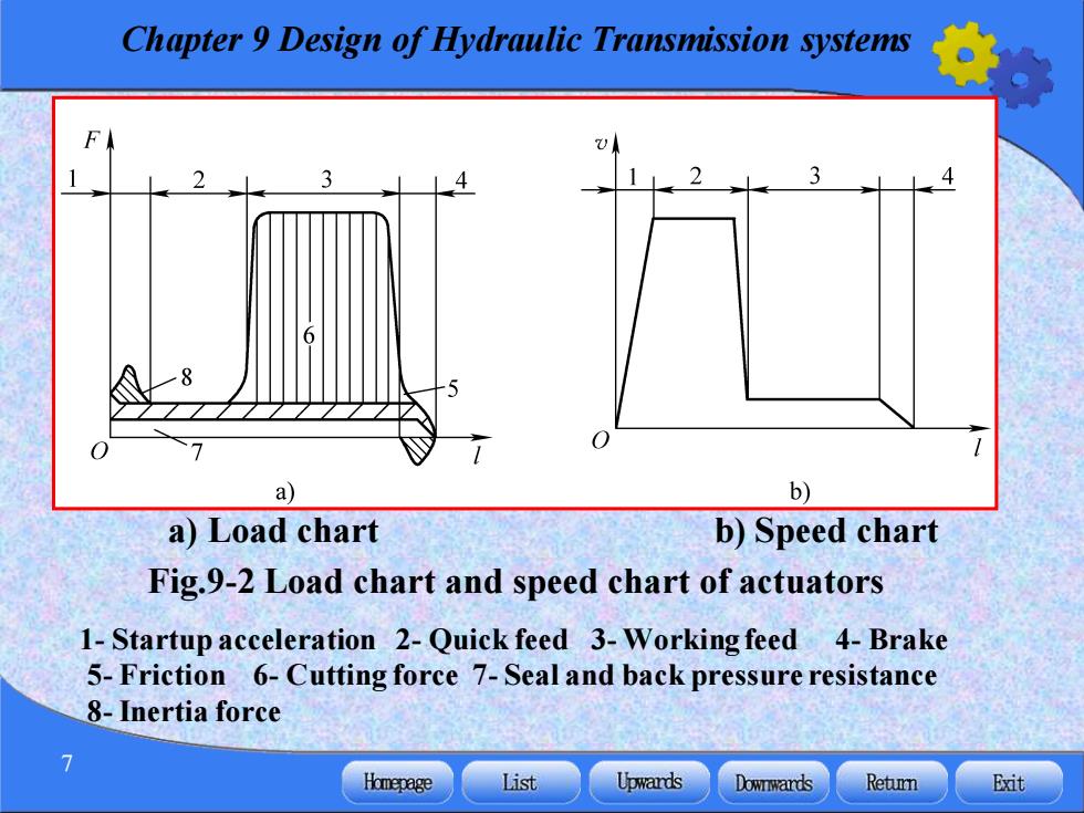
Chapter 9 Design of Hydraulic Transmission systems 7 a) Load chart b) Speed chart Fig.9-2 Load chart and speed chart of actuators 1- Startup acceleration 2- Quick feed 3- Working feed 4- Brake 5- Friction 6- Cutting force 7- Seal and back pressure resistance 8-Inertia force

Chapter 9 Design of Hydraulic Transmission systems 2)Movement parameters analysis Fig.9-2b is a speed-displacement (v-1)curve drawn to express the speed of each actuator in different phases,it is called speed chart. When the actuator works in line reciprocating,the extrinsic load will be F=F+F+F (9-1) (1)The working load F Homepage List Upwards Downwards Retumn Exit
Chapter 9 Design of Hydraulic Transmission systems 8 2)Movement parameters analysis Fig.9-2b is a speed-displacement (v-l)curve drawn to express the speed of each actuator in different phases, it is called speed chart. When the actuator works in line reciprocating, the extrinsic load will be F F F F = + + L f a (9-1) (1) The working load FL
Chapter 9 Design of Hydraulic Transmission systems (2)The friction resistance force F F=fFN (9-2) (3)The inertia load F G△v F =ma= 一X (9-3) 8 △t Besides three loads mentioned above,an actuator stands also viscosity resistance force,sealed resistance force and back pressure resistance etc. Homepage List Upwards Downwards Retumn Exit
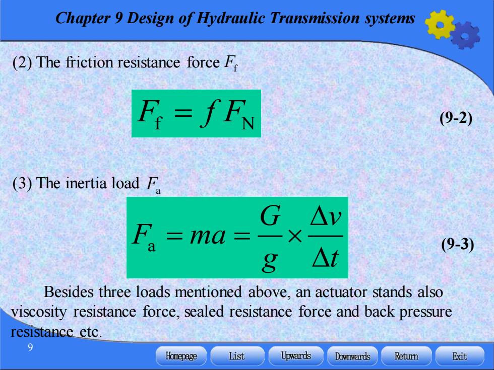
Chapter 9 Design of Hydraulic Transmission systems 9 (2) The friction resistance force Ff F f F f N = (9-2) (3) The inertia load Fa Besides three loads mentioned above, an actuator stands also viscosity resistance force, sealed resistance force and back pressure resistance etc. a (9-3) G v F ma g t = =
Chapter 9 Design of Hydraulic Transmission systems 2.Determination of main parameters The working pressure for actuators can be selected according to the largest load in the load chart(see Tab.9-1)or the mainframe type(see Tab.9-2).However the largest flow rate must be calculated by the highest speed shown in the speed chart. The lowest working speed vinor i(n=2min/60) must satisfy the following requirements: For cylinders ∠Vmin For motors qmin≤0min M 10 Homepage List Upwards Downwards Retumn Exit
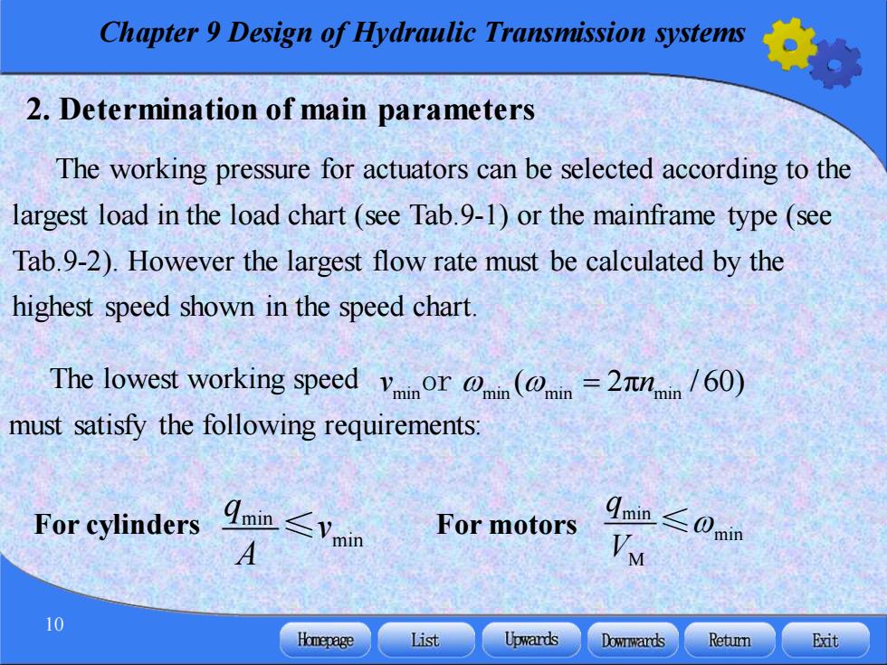
Chapter 9 Design of Hydraulic Transmission systems 10 2. Determination of main parameters The working pressure for actuators can be selected according to the largest load in the load chart (see Tab.9-1) or the mainframe type (see Tab.9-2). However the largest flow rate must be calculated by the highest speed shown in the speed chart. The lowest working speed must satisfy the following requirements: min min q v A ≤ min min M q V For cylinders For motors ≤ min min min min v n or ( 2 = π / 60)