e 90 10 90 Figure 12.3.2 Phasor diagrams for the relationships between current and voltage in (a) the resistor,(b)the inductor,and(c)the capacitor,of a series RLC circuit. From Figure 12.3.2,the instantaneous voltages can be obtained as: Vg(t)=IoRsin @t=Vgo sin @t V()=1X:sint+ (12.3.9) 2 V()sinr- -Vco cos@t where VRO=I0R,VLo=I0X1>VCo=l0Xc (12.3.10) are the amplitudes of the voltages across the circuit elements.The sum of all three voltages is equal to the instantaneous voltage supplied by the AC source: V(t)=VR(t)+V(t)+Vc(t) (12.3.11) Using the phasor representation,the above expression can also be written as Fo=FRo+VLo+VCo (12.3.12) as shown in Figure 12.3.3(a).Again we see that current phasor 1 leads the capacitive voltage phasor oby /2 but lags the inductive voltage phasor o by /2.The three voltage phasors rotate counterclockwise as time passes,with their relative positions fixed. 12-11
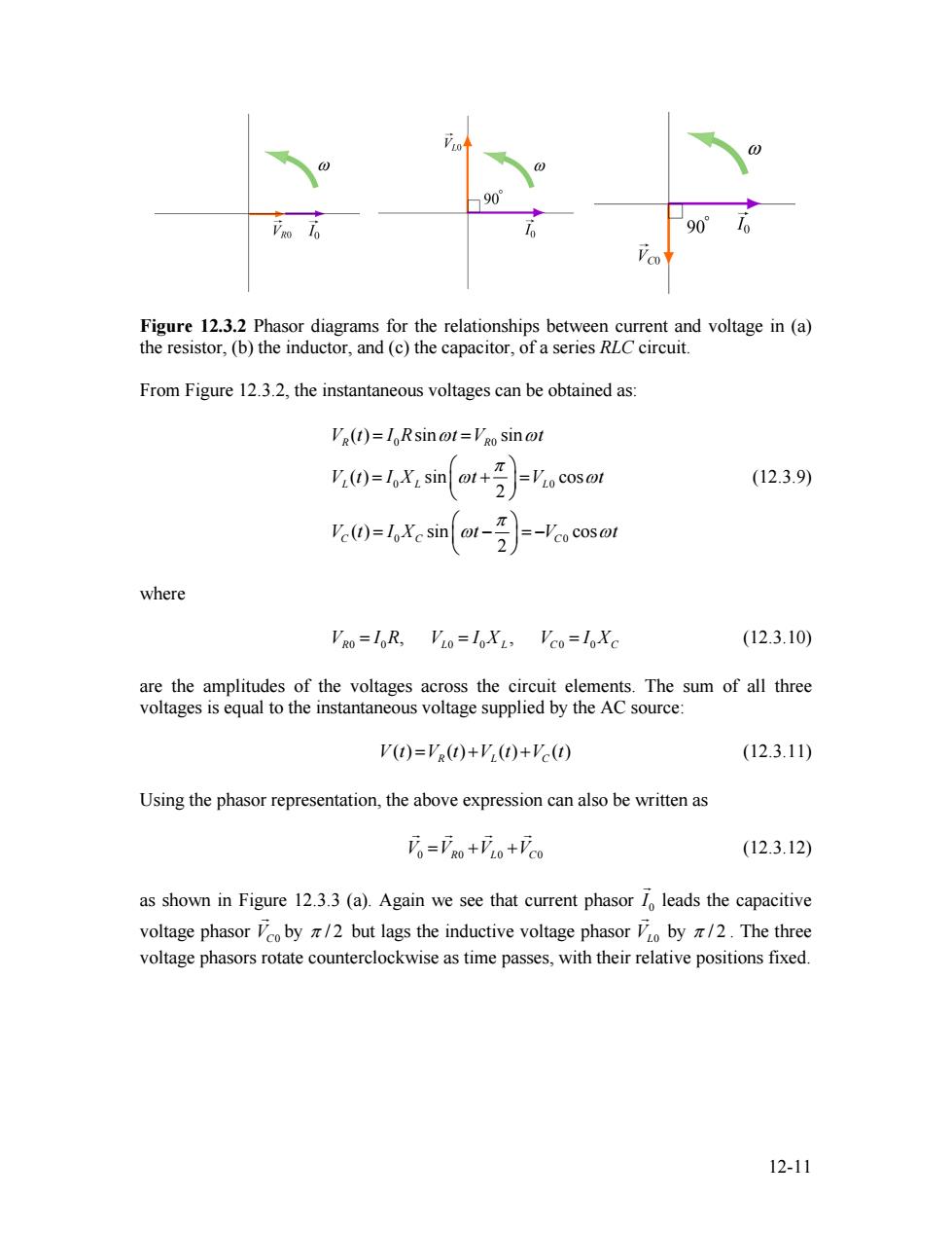
Figure 12.3.2 Phasor diagrams for the relationships between current and voltage in (a) the resistor, (b) the inductor, and (c) the capacitor, of a series RLC circuit. From Figure 12.3.2, the instantaneous voltages can be obtained as: 0 0 0 0 0 0 ( ) sin sin ( ) sin cos 2 ( ) sin cos 2 R R L L L C C C V t I R t V t V t I X t V t V t I X t V t ω ω π ω π ω ω ω = = ⎛ ⎞ = + ⎜ ⎟ = ⎝ ⎠ ⎛ ⎞ = − ⎜ ⎟ = − ⎝ ⎠ (12.3.9) where (12.3.10) 0 0 0 0 0 0 , , V I R L R V L C = = I X V = I XC are the amplitudes of the voltages across the circuit elements. The sum of all three voltages is equal to the instantaneous voltage supplied by the AC source: ( ) ( ) ( ) ( ) V t VR L C = t + + V t V t (12.3.11) Using the phasor representation, the above expression can also be written as V V 0 0 = + R L V 0 +VC0 G G G G (12.3.12) as shown in Figure 12.3.3 (a). Again we see that current phasor 0 I G leads the capacitive voltage phasor by VC0 G π / 2 but lags the inductive voltage phasor VL0 G by π / 2 . The three voltage phasors rotate counterclockwise as time passes, with their relative positions fixed. 12-11
LO VLO-Vco Vo 10 VRO Figure 12.3.3 (a)Phasor diagram for the series RLC circuit.(b)voltage relationship The relationship between different voltage amplitudes is depicted in Figure 12.3.3(b). From the Figure,we see that 。=l=o+o+col=Vo+(Wo-'co月 =VR)2+(X2-1Xc)2 (12.3.13) =loVR2+(XL-Xc) which leads to the same expression for lo as that obtained in Eq.(12.3.7) It is crucial to note that the maximum amplitude of the AC voltage source is not equal to the sum of the maximum voltage amplitudes across the three circuit elements: V。≠VRo+'o+'co (12.3.14) This is due to the fact that the voltages are not in phase with one another,and they reach their maxima at different times. 12.3.1 Impedance We have already seen that the inductive reactance X,=oL and capacitance reactance X=1/@C play the role of an effective resistance in the purely inductive and capacitive circuits,respectively.In the series RLC circuit,the effective resistance is the impedance, defined as Z=/R2+(X:-Xc) (12.3.15) The relationship between Z,XL and Xc can be represented by the diagram shown in Figure 12.3.4: 12-12
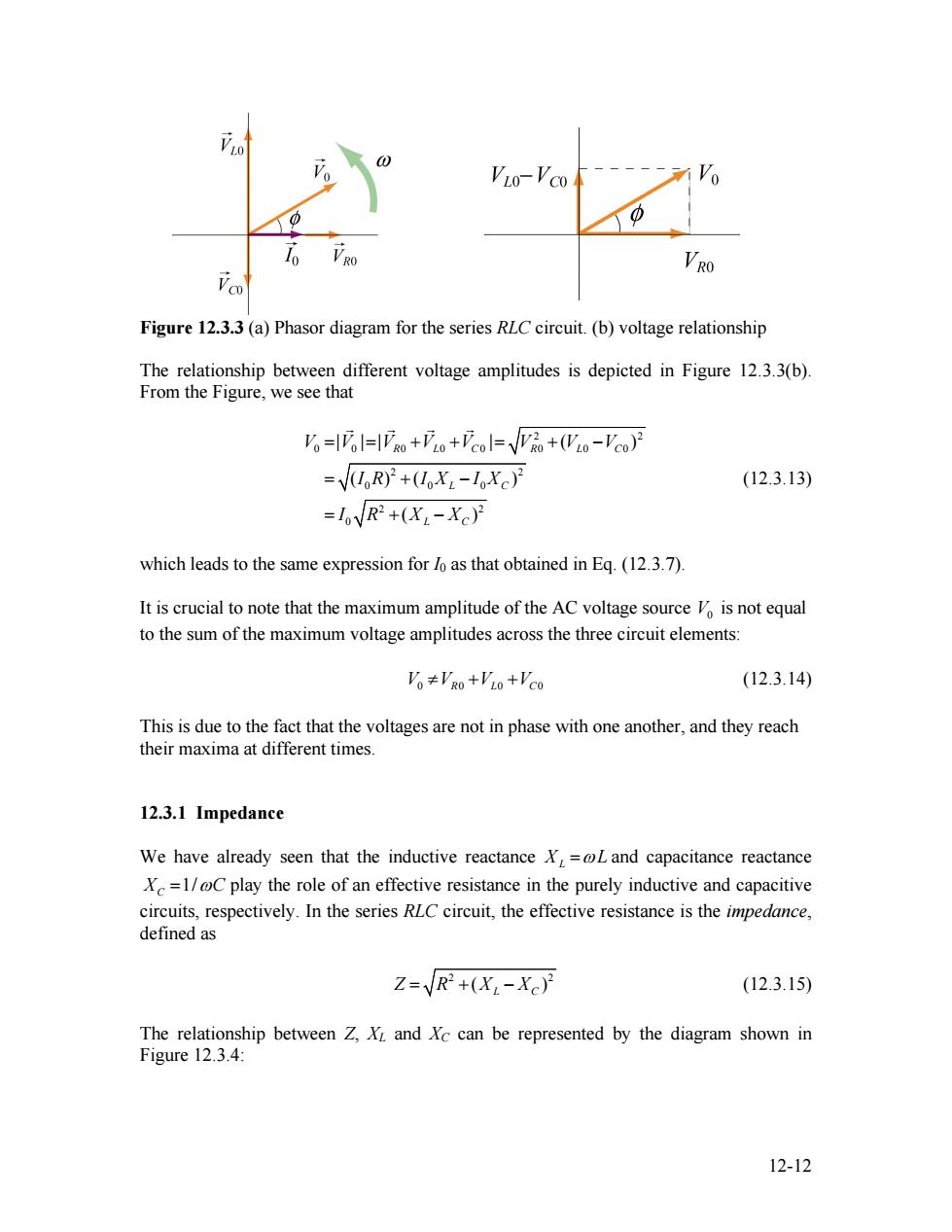
Figure 12.3.3 (a) Phasor diagram for the series RLC circuit. (b) voltage relationship The relationship between different voltage amplitudes is depicted in Figure 12.3.3(b). From the Figure, we see that 2 2 0 0 0 0 0 0 0 0 2 2 0 0 0 2 2 0 | | | | ( ) ( ) ( ) ( ) R L C R L C L C L C V V V V V V V V I R I X I X I R X X = = + + = + − = + − = + − G G G G (12.3.13) which leads to the same expression for I0 as that obtained in Eq. (12.3.7). It is crucial to note that the maximum amplitude of the AC voltage source is not equal to the sum of the maximum voltage amplitudes across the three circuit elements: V0 V V 0 0 ≠ R L + + V 0 VC0 (12.3.14) This is due to the fact that the voltages are not in phase with one another, and they reach their maxima at different times. 12.3.1 Impedance We have already seen that the inductive reactance XL =ωL and capacitance reactance 1/ XC = ωC play the role of an effective resistance in the purely inductive and capacitive circuits, respectively. In the series RLC circuit, the effective resistance is the impedance, defined as 2 ( Z R = + XL − XC 2 ) (12.3.15) The relationship between Z, XL and XC can be represented by the diagram shown in Figure 12.3.4: 12-12
XL-Xc R Figure 12.3.4 Diagrammatic representation of the relationship between Z,X,and X The impedance also has SI units of ohms.In terms of Z,the current may be rewritten as I0=台-sin(o1-) (12.3.16 Notice that the impedance Z also depends on the angular frequency @as do XL and Xc. Using Eq.(12.3.6)for the phase and Eq.(12.3.15)for Z,we may readily recover the limits for simple circuit(with only one element).A summary is provided in Table 12.1 below: Simple C Circuit R L XL=0L Xc= OC Z=yR2+(XL-Xc) purely R 0 00 0 0 0 resistive R purely 0 inductive L 00 XL 0 π/2 X purely capacitive 0 0 C 0 Xc -π/2 Xc Table 12.1 Simple-circuit limits of the series RLC circuit 12.3.2 Resonance Eq.(12.3.15)indicates that the amplitude of the current 1=/Zreaches a maximum when Z is at a minimum.This occurs when X.=Xc,or L=1/@C,leading to 1 0o-JIC (12.3.17) The phenomenon at which reaches a maximum is called a resonance,and the frequency @o is called the resonant frequency.At resonance,the impedance becomes Z=R,the amplitude of the current is 12-13
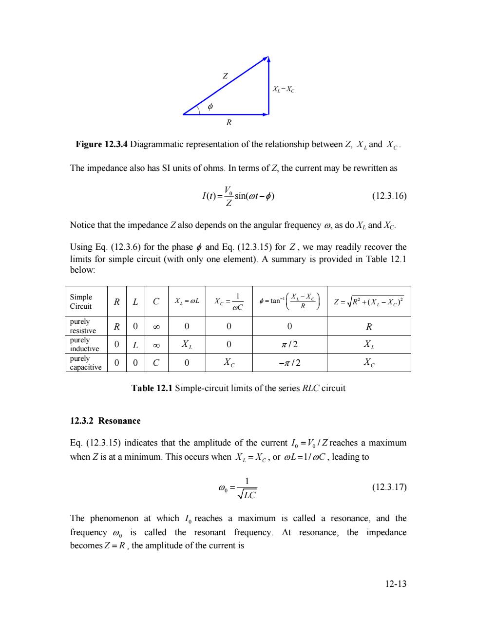
Figure 12.3.4 Diagrammatic representation of the relationship between Z, XL and XC . The impedance also has SI units of ohms. In terms of Z, the current may be rewritten as 0 ( ) sin( ) V I t t Z = ω −φ (12.3.16) Notice that the impedance Z also depends on the angular frequency ω, as do XL and XC. Using Eq. (12.3.6) for the phase φ and Eq. (12.3.15) for Z , we may readily recover the limits for simple circuit (with only one element). A summary is provided in Table 12.1 below: Simple Circuit R L C XL =ωL 1 X C ωC = 1 tan X X L C R φ − ⎛ ⎞ − = ⎜ ⎟ ⎝ ⎠ 2 2 ( ) Z R = + XL C − X purely resistive R 0 ∞ 0 0 0 R purely inductive 0 L ∞ XL 0 π / 2 XL purely capacitive 0 0 C 0 XC −π / 2 XC Table 12.1 Simple-circuit limits of the series RLC circuit 12.3.2 Resonance Eq. (12.3.15) indicates that the amplitude of the current 0 0 I =V / Z reaches a maximum when Z is at a minimum. This occurs when XL = XC , or ωL =1/ωC , leading to 0 1 LC ω = (12.3.17) The phenomenon at which 0 I reaches a maximum is called a resonance, and the frequency ω0 is called the resonant frequency. At resonance, the impedance becomes Z = R , the amplitude of the current is 12-13
1= (12.3.18) R and the phase is 中=0 (12.3.19) as can be seen from Eq.(12.3.5).The qualitative behavior is illustrated in Figure 12.3.5. 16 R2>R1 Figure 12.3.5 The amplitude of the current as a function of in the driven RLC circuit. 12.4 Power in an AC circuit In the series RLC circuit,the instantaneous power delivered by the AC generator is given by Pg=00-=之no--6ma isin(o-)sin of Z (12.4.1) -艺((n4-i列 where we have used the trigonometric identity sin(ot-d)=sinot coso-cosotsin (12.4.2) The time average of the power is 12-14
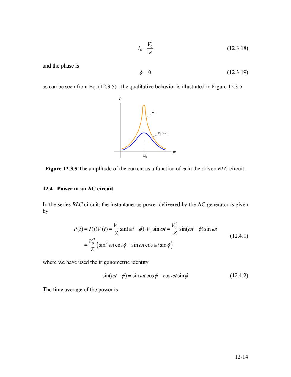
0 0 V I R = (12.3.18) and the phase is 0 φ = (12.3.19) as can be seen from Eq. (12.3.5). The qualitative behavior is illustrated in Figure 12.3.5. Figure 12.3.5 The amplitude of the current as a function of ω in the driven RLC circuit. 12.4 Power in an AC circuit In the series RLC circuit, the instantaneous power delivered by the AC generator is given by ( ) 2 0 0 0 2 0 2 ( ) ( ) ( ) sin( ) sin sin( )sin sin cos sin cos sin V V P t I t V t t V t t t Z Z V t t t Z ω φ ω ω φ ω φ ω ω φ = = − ⋅ = − = − ω (12.4.1) where we have used the trigonometric identity sin(ωt t −φ ω ) = − sin cosφ cosωtsinφ (12.4.2) The time average of the power is 12-14