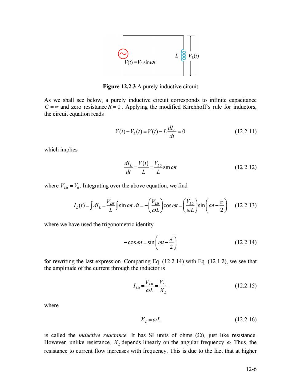
V(t)=Vo sin@t Figure 12.2.3 A purely inductive circuit As we shall see below,a purely inductive circuit corresponds to infinite capacitance C=oo and zero resistance R=0.Applying the modified Kirchhoff's rule for inductors, the circuit equation reads P)-y20=p0-L业=0 (12.2.11) dt which implies dlL-V④_'sinot (12.2.12) dt LL where Vo=Vo.Integrating over the above equation,we find (12.2.13) where we have used the trigonometric identity -cosot=sin @1- (12.2.14) for rewriting the last expression.Comparing Eq.(12.2.14)with Eq.(12.1.2),we see that the amplitude of the current through the inductor is L0= OL XL (12.2.15) where XL=@L (12.2.16) is called the inductive reactance.It has SI units of ohms ()just like resistance. However,unlike resistance,X,depends linearly on the angular frequency @Thus,the resistance to current flow increases with frequency.This is due to the fact that at higher 12-6
Figure 12.2.3 A purely inductive circuit As we shall see below, a purely inductive circuit corresponds to infinite capacitance and zero resistance . Applying the modified Kirchhoff’s rule for inductors, the circuit equation reads C = ∞ R = 0 ( ) ( ) ( ) 0 L L dI V t V t V t L dt − = − = (12.2.11) which implies 0 ( ) sin dIL V t VL t dt L L = = ω (12.2.12) where . Integrating over the above equation, we find VL0 =V0 0 0 0 ( ) sin cos sin 2 L L L L L V V V I t dI t dt t t L L L π ω ω ω ω ⎛ ⎞ ⎛ ⎞ ⎛ = = = − = ⎜ − ⎜ ⎟ ⎜ ⎟ ⎝ ⎠ ⎝ ⎠ ⎝ ⎠ ∫ ∫ ω ⎞ ⎟ (12.2.13) where we have used the trigonometric identity cos sin 2 t t π ω ω ⎛ − = ⎜ − ⎝ ⎠ ⎞ ⎟ (12.2.14) for rewriting the last expression. Comparing Eq. (12.2.14) with Eq. (12.1.2), we see that the amplitude of the current through the inductor is 0 0 L L L L V V I ωL X = = 0 (12.2.15) where XL =ωL (12.2.16) is called the inductive reactance. It has SI units of ohms (Ω), just like resistance. However, unlike resistance, XL depends linearly on the angular frequency ω. Thus, the resistance to current flow increases with frequency. This is due to the fact that at higher 12-6

frequencies the current changes more rapidly than it does at lower frequencies.On the other hand,the inductive reactance vanishes as approaches zero. By comparing Eq.(12.2.14)to Eq.(12.1.2),we also find the phase constant to be (12.2.17) The current and voltage plots and the corresponding phasor diagram are shown in the Figure 12.2.4 below. I() Figure 12.2.4 (a)Time dependence of I(t)and V(t)across the inductor.(b)Phasor diagram for the inductive circuit. As can be seen from the figures,the current I(t)is out of phase with V(t)by =z/2; it reaches its maximum value after V(t)does by one quarter of a cycle.Thus,we say that The current lags voltage by /2 in a purely inductive circuit 12.2.3 Purely Capacitive Load In the purely capacitive case,both resistance R and inductance L are zero.The circuit diagram is shown in Figure 12.2.5. Vc(t) V(t)=Vosin@t Figure 12.2.5 A purely capacitive circuit 12-7
frequencies the current changes more rapidly than it does at lower frequencies. On the other hand, the inductive reactance vanishes as ω approaches zero. By comparing Eq. (12.2.14) to Eq. (12.1.2), we also find the phase constant to be 2 π φ = + (12.2.17) The current and voltage plots and the corresponding phasor diagram are shown in the Figure 12.2.4 below. Figure 12.2.4 (a) Time dependence of ( ) L I t and ( ) VL t across the inductor. (b) Phasor diagram for the inductive circuit. As can be seen from the figures, the current ( ) L I t is out of phase with ( ) by VL t φ = π / 2 ; it reaches its maximum value after ( ) does by one quarter of a cycle. Thus, we say that VL t The current lags voltage by π / 2 in a purely inductive circuit 12.2.3 Purely Capacitive Load In the purely capacitive case, both resistance R and inductance L are zero. The circuit diagram is shown in Figure 12.2.5. Figure 12.2.5 A purely capacitive circuit 12-7

Again,Kirchhoff's voltage rule implies )-Ve(0=r0-0=0 (12.2.18) which yields Q(t)=CV(t)=CVc(t)=CVco sin@t (12.2.19) where Vco=.On the other hand,the current is (12.2.20) d where we have used the trigonometric identity cosot sin 0t+ (12.2.21) 2 The above equation indicates that the maximum value of the current is Ico =@CVco=- (12.2.22) Xc where 1 Xc=- (12.2.23) OC is called the capacitance reactance.It also has SI units of ohms and represents the effective resistance for a purely capacitive circuit.Note that X is inversely proportional to both C andand diverges as approaches zero. By comparing Eq.(12.2.21)to Eq.(12.1.2),the phase constant is given by (12.2.24) 2 The current and voltage plots and the corresponding phasor diagram are shown in the Figure 12.2.6 below. 12-8
Again, Kirchhoff’s voltage rule implies ( ) ( ) ( ) ( ) 0 C Q t V t V t V t C − = − = (12.2.18) which yields 0 ( ) ( ) ( ) sin Q C C t = = CV t CV t =CV ωt (12.2.19) where . On the other hand, the current is VC0 =V0 0 0 ( ) cos sin 2 C C C dQ I t CV t CV t dt π ω ω ω ω ⎛ = + = = ⎜ + ⎝ ⎠ ⎞ ⎟ (12.2.20) where we have used the trigonometric identity cos sin 2 t t π ω ω ⎛ = ⎜ + ⎝ ⎠ ⎞ ⎟ (12.2.21) The above equation indicates that the maximum value of the current is 0 0 0 C C C C V I CV X =ω = (12.2.22) where 1 XC ωC = (12.2.23) is called the capacitance reactance. It also has SI units of ohms and represents the effective resistance for a purely capacitive circuit. Note that XC is inversely proportional to both C and ω , and diverges as ω approaches zero. By comparing Eq. (12.2.21) to Eq. (12.1.2), the phase constant is given by 2 π φ = − (12.2.24) The current and voltage plots and the corresponding phasor diagram are shown in the Figure 12.2.6 below. 12-8
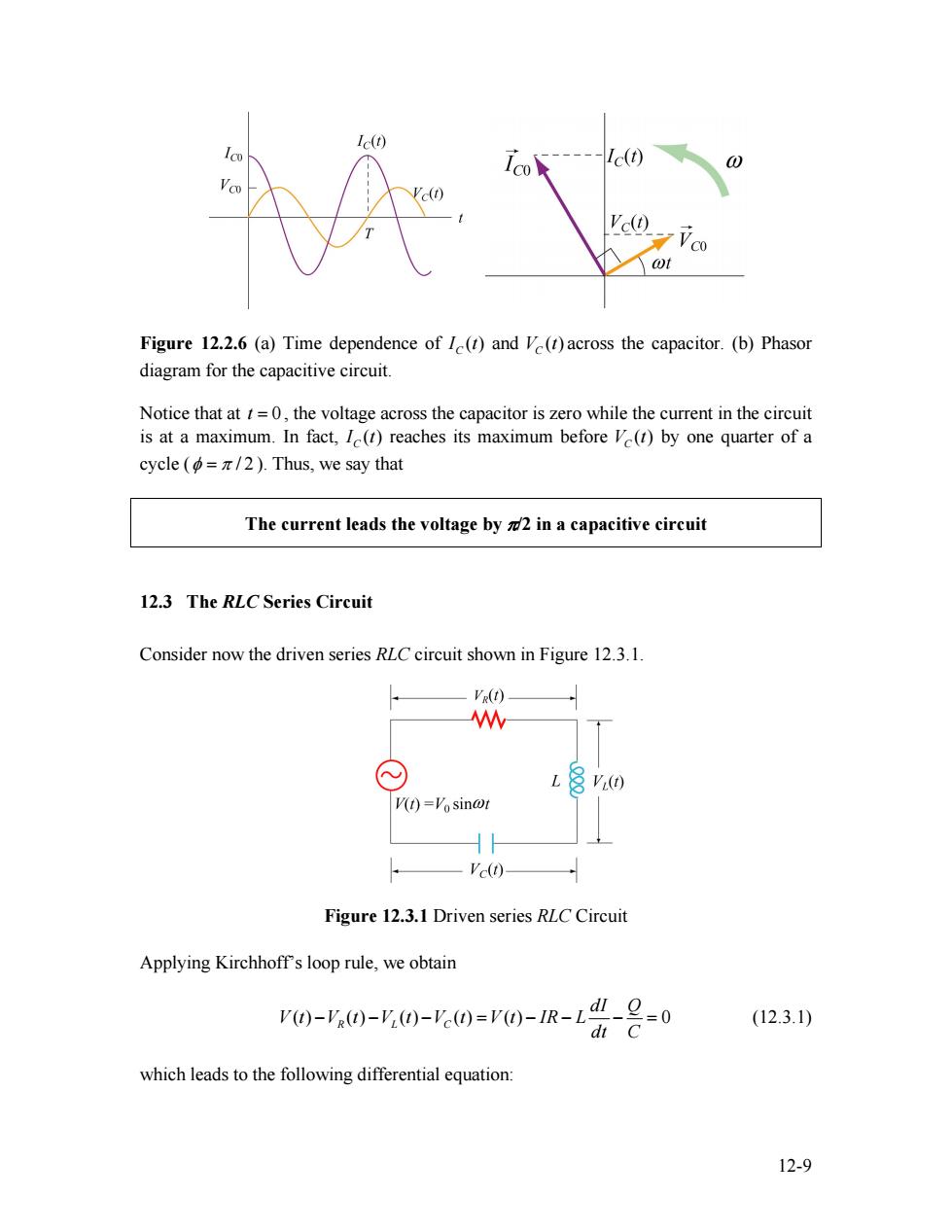
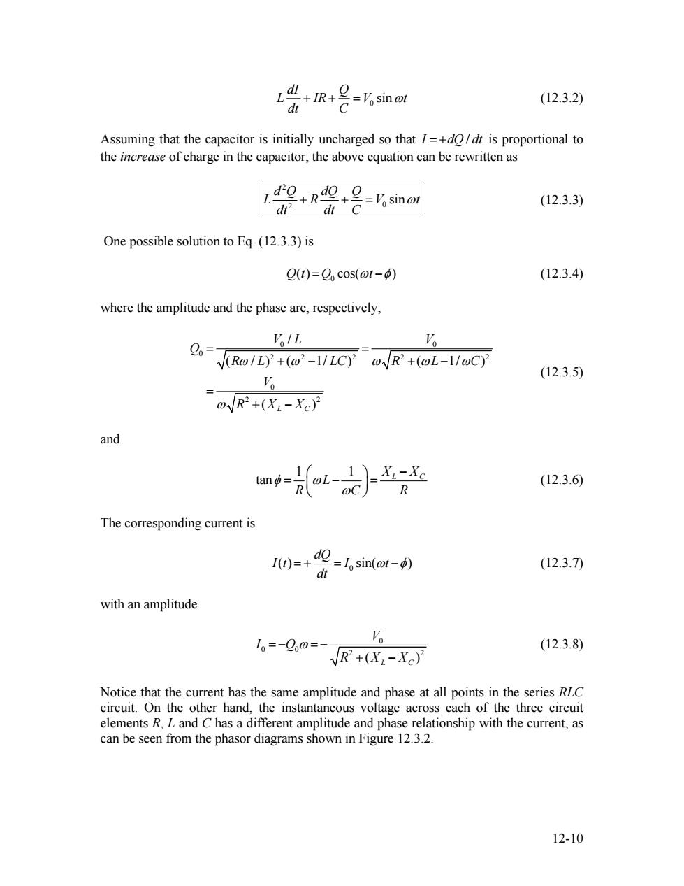
Ic(t) Ic(t) 0 Ve(t) ¥C0 wt Figure 12.2.6 (a)Time dependence of I(t)and V(t)across the capacitor.(b)Phasor diagram for the capacitive circuit. Notice that at t=0,the voltage across the capacitor is zero while the current in the circuit is at a maximum.In fact,I(t)reaches its maximum before V(t)by one quarter of a cycle (=/2).Thus,we say that The current leads the voltage by 2 in a capacitive circuit 12.3 The RLC Series Circuit Consider now the driven series RLC circuit shown in Figure 12.3.1. VR(t) W V(t)=Vosin@t Ve(t) Figure 12.3.1 Driven series RLC Circuit Applying Kirchhoffs loop rule,we obtain V)-'0)-y(0-0=r0-1R-L"-2=0 (12.3.1) dt C which leads to the following differential equation: 12-9
Figure 12.2.6 (a) Time dependence of ( ) CI t and across the capacitor. (b) Phasor diagram for the capacitive circuit. ( ) VC t Notice that at , the voltage across the capacitor is zero while the current in the circuit is at a maximum. In fact, t = 0 ( ) CI t reaches its maximum before by one quarter of a cycle ( ( ) VC t φ = π / 2 ). Thus, we say that The current leads the voltage by π/2 in a capacitive circuit 12.3 The RLC Series Circuit Consider now the driven series RLC circuit shown in Figure 12.3.1. Figure 12.3.1 Driven series RLC Circuit Applying Kirchhoff’s loop rule, we obtain ( ) ( ) ( ) ( ) ( ) 0 R L C dI Q V t V t V t V t V t IR L dt C − − − = − − − = (12.3.1) which leads to the following differential equation: 12-9
+I-Vosinot (12.3.2) d Assuming that the capacitor is initially uncharged so that I=+do/dt is proportional to the increase of charge in the capacitor,the above equation can be rewritten as do +Ra№+9=osinot C (12.3.3) d d One possible solution to Eq.(12.3.3)is Q(t)=Qcos(ot-φp) (12.3.4) where the amplitude and the phase are,respectively, '%/L Vo R-VLCy @R2+(@L-1/@C) (12.3.5) oVR2+(X-Xc)月 and tand= oi-nc (12.3.6) R @C The corresponding current is I()= d-l,sin(@t--p) (12.3.7) dt with an amplitude 10=-Qo0=- a (12.3.8) VR+(X-Xc)2 Notice that the current has the same amplitude and phase at all points in the series RLC circuit.On the other hand,the instantaneous voltage across each of the three circuit elements R,L and C has a different amplitude and phase relationship with the current,as can be seen from the phasor diagrams shown in Figure 12.3.2. 12-10
0 sin dI Q L IR V dt C + + = ωt (12.3.2) Assuming that the capacitor is initially uncharged so that I = +dQ / dt is proportional to the increase of charge in the capacitor, the above equation can be rewritten as 2 2 0 sin d Q dQ Q L R V dt dt C + + = ωt (12.3.3) One possible solution to Eq. (12.3.3) is 0 Q t( ) =Q cos(ωt −φ) (12.3.4) where the amplitude and the phase are, respectively, 0 0 0 2 2 2 2 0 2 2 / ( / ) ( 1/ ) ( 1/ ) ( ) L C V L V Q 2 R L LC R L V R X X ω ω ω ω ω ω = = + − + − = + − C (12.3.5) and 1 1 tan XL XC L R C R φ ω ω ⎛ ⎞ − = − ⎜ ⎟ = ⎝ ⎠ (12.3.6) The corresponding current is 0 ( ) sin( ) dQ I t I t dt = + = ω −φ (12.3.7) with an amplitude 0 0 0 2 ( ) L C V I Q R X X = − ω = − + − 2 (12.3.8) Notice that the current has the same amplitude and phase at all points in the series RLC circuit. On the other hand, the instantaneous voltage across each of the three circuit elements R, L and C has a different amplitude and phase relationship with the current, as can be seen from the phasor diagrams shown in Figure 12.3.2. 12-10