
电子科线女学光电科学与工程学院 SCHOOL OF OPTOELECTRONIC SCIENCE AND ENGINEERING OF UESTC 2.Detection of Isolated Points Point detection can be done by applying the thresholding a b function: 1 1 FIGURE 10.4 (a)Point detection 1,R(x,y≥T (Laplacian)mask 8()= -8 (b)X-ray image of turbine blade 10,otherwise with a porosity The porosity contains a single where black pixel. 9 (c)Result of convolving the =∑w2 R mask with the image.(d)Result k=1 of using Eq.(10.2-8) showing a single point (the point Highpass or was enlarged to make it easier to lowpass see).(Original image courtesy of filters? X-TEK Systems, Ltd.)
Point detection can be done by applying the thresholding function: 1, ( , ) ( , ) 0, otherwise R x y T g x y = 9 1 k k k R w z = = where 2. Detection of Isolated Points Highpass or lowpass filters?
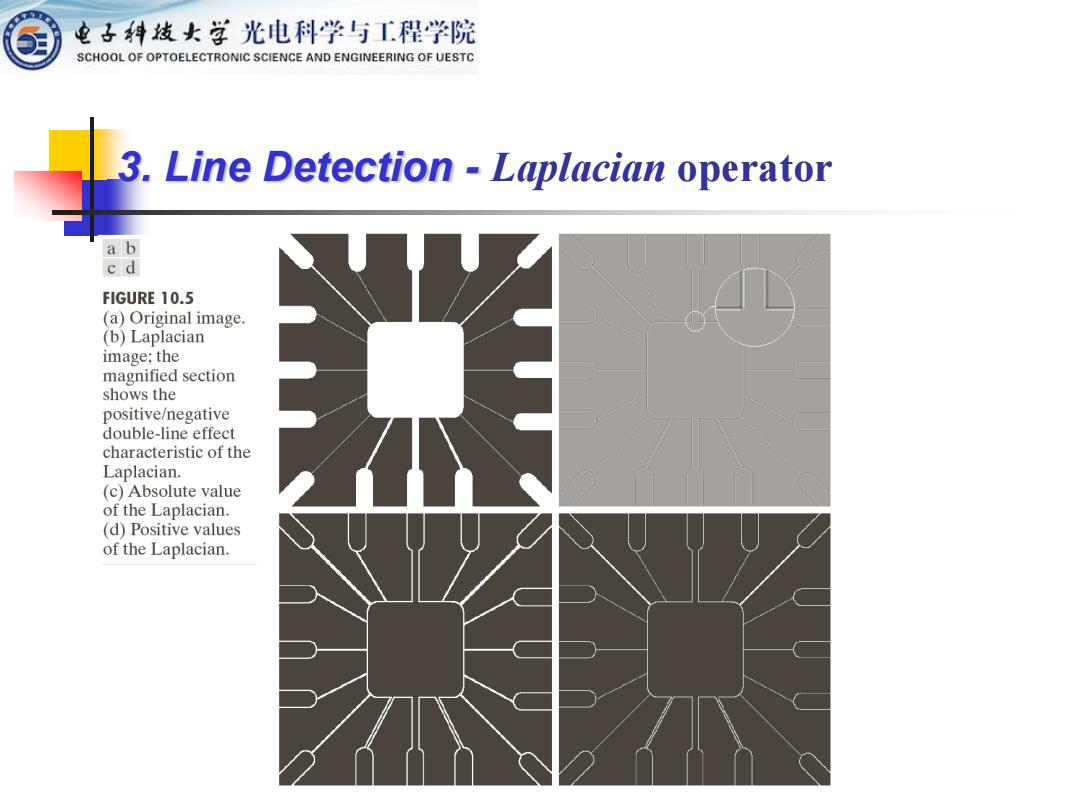
电子科线女学光电科学与工程学院 SCHOOL OF OPTOELECTRONIC SCIENCE AND ENGINEERING OF UESTC 3.Line Detection Laplacian operator ab cd FIGURE 10.5 (a)Original image. (b)Laplacian image;the magnified section shows the positive/negative double-line effect characteristic of the Laplacian. (c)Absolute value of the Laplacian. (d)Positive values of the Laplacian
3. Line Detection - Laplacian operator

电子科发女学光电科学与工程学院 SCHOOL OF OPTOELECTRONIC SCIENCE AND ENGINEERING OF UESTC 3.Line Detection Directional masks Line detection can be performed using the mask the has the shape look similar to a part of a line. For example,4 directions that are mostly used are horizontal. +45 degree,vertical and-45 degree. 2 2 2 2 2 2 -1 -1 2 Horizontal +45 Vertical -450 FIGURE 10.6 Line detection masks.Angles are with respect to the axis system in Fig.2.18(b)
❖ Line detection can be performed using the mask the has the shape look similar to a part of a line. ❖ For example, 4 directions that are mostly used are horizontal, +45 degree, vertical and –45 degree. 3. Line Detection - Directional masks

电子科发女学光电科学与工程学院 SCHOOL OF OPTOELECTRONIC SCIENCE AND ENGINEERING OF UESTC Example:Detection of lines in specified directions ab cd ef ■Masks for lines of FIGURE 10.7 different directions. (a)Image of a wire-bond template. (b)Result of processing with Respond more the+45°line detector mask in strongly to lines of Fig.10.6. one pixel thick of (c)Zoomed view of the top left the designated region of (b). (d)Zoomed view direction. of the bottom right region of (b).(e)The image in (b)with all negative values set to zero.(f)All points (in white) whose values satisfied the condition g≥T, where g is the -1 image in (e).(The points in (f)were enlarged to make them easier to see.)
Example: Detection of lines in specified directions ◼ Masks for lines of different directions. 2 -1 -1 -1 2 -1 -1 -1 2 ◼ Respond more strongly to lines of one pixel thick of the designated direction

电子科线女学光电科学与工程学院 SCHOOL OF OPTOELECTRONIC SCIENCE AND ENGINEERING OF UESTC 3.Edge Models Edge of Image (Objects) Generally,objects and background have different intensities. Edges of the objects are the areas where abrupt intensity changes occur. Edge models Step edge(阶跃边缘) Roofedge(屋顶边缘) Ramp edge(斜坡边缘) Pulse edge(脉冲边缘)一Point or Line
◼ Edge of Image (Objects) Generally, objects and background have different intensities. Edges of the objects are the areas where abrupt intensity changes occur. Edge models Step edge(阶跃边缘) Roof edge(屋顶边缘) Ramp edge(斜坡边缘) Pulse edge(脉冲边缘)—— Point or Line 3. Edge Models