
Chapter 7 Basic Hydraulic Circuits 2.A pressure-holding circuits by the accumulator As shown in fig.7-6b. 3.A pressure holding by the auxiliary pump As shown in fig.7-6c. 16 Homepage List Upwards Downwards Retun E☒t
Chapter 7 Basic Hydraulic Circuits 16 2. A pressure-holding circuits by the accumulator As shown in fig.7-6b. 3. A pressure holding by the auxiliary pump As shown in fig.7-6c
Chapter 7 Basic Hydraulic Cireuits 7.2 Speed Control Circuits Speed control circuits,are the important parts in a hydraulic system,aim at regulating the motion speed of the actuator elements. 7.2.1 The principles of speed-regulating and control 7.2.2 Throttle speed-regulating circuits by a invariable displacement pump 7.2.3 Volume speed-regulating circuits 7.2.4 Fast-speed movement circuits 7.2.5 Speed shift circuit 17 Homepage List Upwards Downwards Retun Exit
Chapter 7 Basic Hydraulic Circuits 17 7.2 Speed Control Circuits 7.2.1 The principles of speed-regulating and control 7.2.2 Throttle speed-regulating circuits by a invariable displacement pump 7.2.3 Volume speed-regulating circuits 7.2.4 Fast-speed movement circuits 7.2.5 Speed shift circuit Speed control circuits, are the important parts in a hydraulic system, aim at regulating the motion speed of the actuator elements
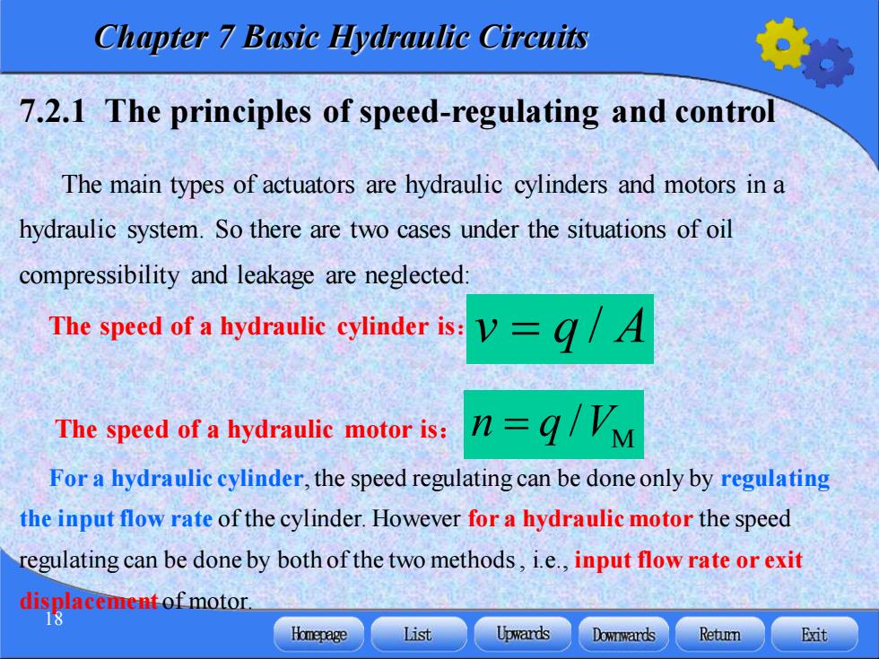
Chapter 7 Basic Hydraulic Circuits 7.2.1 The principles of speed-regulating and control The main types of actuators are hydraulic cylinders and motors in a hydraulic system.So there are two cases under the situations of oil compressibility and leakage are neglected: The speed of a hydraulic cylinder is: =q/A The speed of a hydraulic motor is: n=q/Vm For a hydraulic cylinder,the speed regulating can be done only by regulating the input flow rate of the cylinder.However for a hydraulic motor the speed regulating can be done by both of the two methods,i.e.,input flow rate or exit displacement ofmotor. Homepage List Upwards Downwards Retumn Exit
Chapter 7 Basic Hydraulic Circuits 18 7.2.1 The principles of speed-regulating and control The main types of actuators are hydraulic cylinders and motors in a hydraulic system. So there are two cases under the situations of oil compressibility and leakage are neglected: The speed of a hydraulic cylinder is: The speed of a hydraulic motor is: v = q / A M n q V = / For a hydraulic cylinder, the speed regulating can be done only by regulating the input flow rate of the cylinder. However for a hydraulic motor the speed regulating can be done by both of the two methods , i.e., input flow rate or exit displacement of motor
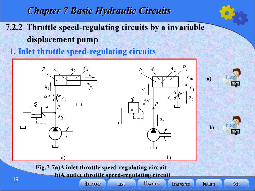
Chapter 7 Basie Hydraulic Circuits 7.2.2 Throttle speed-regulating circuits by a invariable displacement pump 1.Inlet throttle speed-regulating circuits A P2 DVD △9 Play DVD b Fig.7-7a)A inlet throttle speed-regulating circuit b)A outlet throttle speed-regulating circuit 19 Homepage List Upwards Downwards Retumn Exit
Chapter 7 Basic Hydraulic Circuits 19 1. Inlet throttle speed-regulating circuits Fig.7-7a)A inlet throttle speed-regulating circuit b)A outlet throttle speed-regulating circuit 7.2.2 Throttle speed-regulating circuits by a invariable displacement pump a) b)

Chapter 7 Basic Hydraulie Circuits (1)The features of speed-load The motion speed of a hydraulic cylinder is v=91/A (7-1) Flowing rate into the throttle orifice valve is: =KLAVAP=KLATVPs-Pr (7-2) Then the force balance equation in piston is PA=B2A+F (7-3) If the oil flows directly to the reservoir,p2=0,then p=F/4=PL Substituting into formula(7-2)we obtain, 20 Homepage List Upwards Downwards Retumn Exit
Chapter 7 Basic Hydraulic Circuits 20 (1)The features of speed-load The motion speed of a hydraulic cylinder is : Flowing rate into the throttle orifice valve is: 1 1 v = q / A (7-1) 1 L T L T s 1 q K A p K A p p = = − (7-2) Then the force balance equation in piston is 1 1 2 2 L p A p A F = + (7-3) If the oil flows directly to the reservoir, ,then Substituting into formula (7-2) we obtain, p2 = 0 1 L 1 L p F A p = = /