
FluorChem System Setup page 11 Screws Figure I-5:Camera Installation-Step I 2.Place the o-ring in the middle of the bracket O-Ring Figure I-:Camera InstallationStep 2 3.Place the motorized optics onto the bracket,carefully aligning it on top of the two protruding studs.The motorized optics and should fit perfectly.Once on top.use the two fasteners to secure the motorized optics. FluorChem HD2 and FC2 User Guide
FluorChem System Setup page 11 FluorChem HD2 and FC2 User Guide Figure 1-5: Camera Installation—Step 1 2. Place the o-ring in the middle of the bracket. Figure 1-6: Camera Installation—Step 2 3. Place the motorized optics onto the bracket, carefully aligning it on top of the two protruding studs. The motorized optics and should fit perfectly. Once on top, use the two fasteners to secure the motorized optics
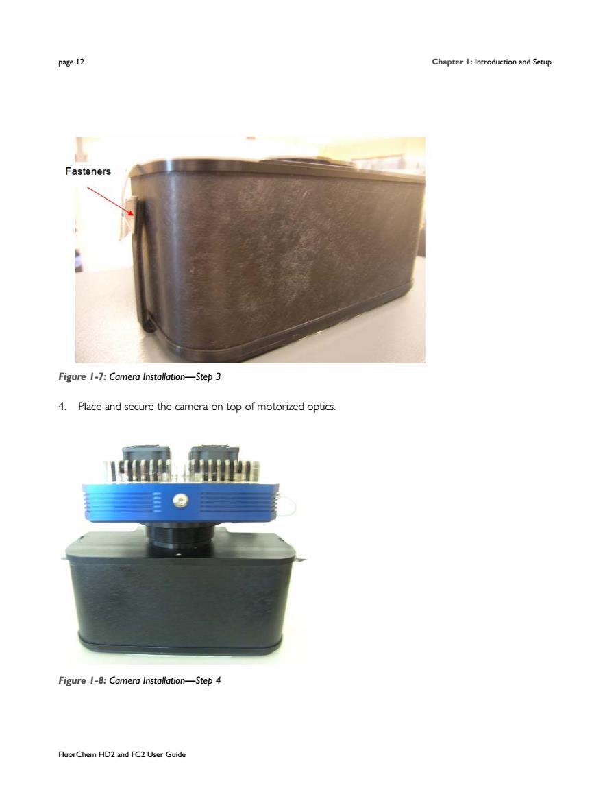
page 2 Chapter:and Setup Fasteners Figure I-7:Camera Installation-Step3 4.Place and secure the camera on top of motorized optics. 居 Figure-:Camera Installation-Step4 FluorChem HD2 and FC2 User Guide
page 12 Chapter 1: Introduction and Setup FluorChem HD2 and FC2 User Guide Figure 1-7: Camera Installation—Step 3 4. Place and secure the camera on top of motorized optics. Figure 1-8: Camera Installation—Step 4

FluorChem System Setup page 13 CAUTION Install two20x 1/4"button head screws on the camera sides to prevent light leaks.Do not use screws longer then 3/8"or the camera will be damaged. 1.Connect the camera cable and the camera power supply connectors to the back side of the camera. Figure 1-9:Camera Setup-Step I 2.Connect the power cable standard three-prong end to the power strip. Figure 1-10:Camera Setup-Step 2 FluorChem HD2 and FC2 User Guide
FluorChem System Setup page 13 FluorChem HD2 and FC2 User Guide CAUTION Install two ¼”-20 x 1/4” button head screws on the camera sides to prevent light leaks. Do not use screws longer then 3/8” or the camera will be damaged. 1. Connect the camera cable and the camera power supply connectors to the back side of the camera. Figure 1-9: Camera Setup—Step 1 2. Connect the power cable standard three-prong end to the power strip. Figure 1-10: Camera Setup—Step 2
page 14 Chapter and Setup 3.Complete the installation by connecting the camera cable to the USB port d Figure I-II:Camera Setup-Step 3 Connecting the Printer The Mitsubishi P95DW(UB)printer connections are color-coded for convenience.Plug the USB cable into the back of the printer and into the proper USB connector on the back of the computer.Plug in the standard three-prong power cable to the back of the printer and to the power strip.then tumn the power on. NOTE:The printer may be connected to any USB port on the computer;however,the driver may need to be manually re-installed depending on which USB port is used. The Mitsubishi CP700 and CP770 printers connect via the on-board parallel (LPTI)port Plug in the standard three-prong power cable on the back of the printer and into the power strip,then turn the power on.Set the printer up for color or black and white printing following the directions in the owner's manual supplied with the printer Power Up Sequence de6op camera,printer and monitor power can be I.Monitor 2.Computer 3.DE500 cabinet 4.Camera power supply-the camera will begin to cool to-10C. 5.Printer After the cabinet filter wheel has finished homing,launch AlphaView software to begin deep cooling of the camera(minimum cooling period is 30 minutes). FluorChem HD2 and FC2 User Guid
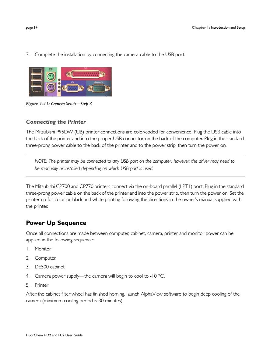
page 14 Chapter 1: Introduction and Setup FluorChem HD2 and FC2 User Guide 3. Complete the installation by connecting the camera cable to the USB port. Figure 1-11: Camera Setup—Step 3 Connecting the Printer The Mitsubishi P95DW (UB) printer connections are color-coded for convenience. Plug the USB cable into the back of the printer and into the proper USB connector on the back of the computer. Plug in the standard three-prong power cable to the back of the printer and to the power strip, then turn the power on. NOTE: The printer may be connected to any USB port on the computer; however, the driver may need to be manually re-installed depending on which USB port is used. The Mitsubishi CP700 and CP770 printers connect via the on-board parallel (LPT1) port. Plug in the standard three-prong power cable on the back of the printer and into the power strip, then turn the power on. Set the printer up for color or black and white printing following the directions in the owner’s manual supplied with the printer. Power Up Sequence Once all connections are made between computer, cabinet, camera, printer and monitor power can be applied in the following sequence: 1. Monitor 2. Computer 3. DE500 cabinet 4. Camera power supply—the camera will begin to cool to -10 °C. 5. Printer After the cabinet filter wheel has finished homing, launch AlphaView software to begin deep cooling of the camera (minimum cooling period is 30 minutes)
FluorChem System Setup Starting the FluorChem System with AlphaView Software To launch AlphaView software,double-click the AlphaView icon on the Windows desktop System Information To display system information,click Help>About This option accesses a pop-up box(see Figure 1-12) Build:0428 Coo210d oK☐ Figure 1-12:System Information This box shows the software version number.Use the information specific to your instrument and software when calling Cell Biosciences for technical support and software upgrades. To close the box,click OK. FluorChem HD2 and FC2 User Guide
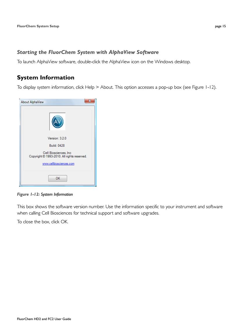
FluorChem System Setup page 15 FluorChem HD2 and FC2 User Guide Starting the FluorChem System with AlphaView Software To launch AlphaView software, double-click the AlphaView icon on the Windows desktop. System Information To display system information, click Help > About. This option accesses a pop-up box (see Figure 1-12). Figure 1-12: System Information This box shows the software version number. Use the information specific to your instrument and software when calling Cell Biosciences for technical support and software upgrades. To close the box, click OK