
page6 Chapter:Se Monitor Port yboardnoUE8o 1日 USB Printer Caw2orMioeg Figure I-:Computer,Monitor,Mouse,and Keyboard Setup Connect the monitor's video cable to the monitor port on the back of the computer.If after-market vided cards were preinstalled into your computer system,connect the monitor's video cable to the video card connector.Connect the monitor's power cable to the power strip. The mouse and keyboard connectors are color-coded and icon identified.Attach the mouse and keyboard cables to the connectors on the back of the computer by matching the colors.Some systems have USB mouse and keyboards. The computer is now ready to be turned on.Tumn the computer on by pushing the power button on the front of the unit FluorChem HD2 and FC2User Guid
page 6 Chapter 1: Introduction and Setup FluorChem HD2 and FC2 User Guide Figure 1-1: Computer, Monitor, Mouse, and Keyboard Setup Connect the monitor’s video cable to the monitor port on the back of the computer. If after-market video cards were preinstalled into your computer system, connect the monitor’s video cable to the video card connector. Connect the monitor’s power cable to the power strip. The mouse and keyboard connectors are color-coded and icon identified. Attach the mouse and keyboard cables to the connectors on the back of the computer by matching the colors. Some systems have USB mouse and keyboards. The computer is now ready to be turned on. Turn the computer on by pushing the power button on the front of the unit

FluorChem System Setup Cabinet Installation Instructions Figure I-2:Multilmage ll Light Cabinet(DE-500)-Pictured with the cabinet top (DE-500FC) Cabinet Setup both packed in separate boxes.Make sure you have received all the hardware before discarding the shipping carton. 1.The largest box will be the DE500 cabinet.This box will include camera bracket,camera bracket gasket RS-232 cable,magnetic pad and pen. 2.Set the entire cabinet assembly on a level,flat surface.(There are indentations to the bottom of the cabinet please use them for lifting and placement of the unit The cabinet with the UV transilluminator please take appropriate precautions in lifting and moving the light cabinet)The footprint dimensions for the cabinet is 20 wide X 14 deep. 3.Open door and remove shipping foam from above and below fold down white light table. FluorChem HD2 and FC2 User Guide
FluorChem System Setup page 7 FluorChem HD2 and FC2 User Guide Cabinet Installation Instructions Figure 1-2: MultiImage II Light Cabinet (DE-500)—Pictured with the cabinet top (DE-500FC) Cabinet Setup When you remove the light cabinet from its shipping carton, it is already partially assembled. The camera mounting assembly is packed separately in the same container. The UV transilluminator and cabinet top are both packed in separate boxes. Make sure you have received all the hardware before discarding the shipping carton. 1. The largest box will be the DE500 cabinet. This box will include camera bracket, camera bracket gasket, RS-232 cable, magnetic pad and pen. 2. Set the entire cabinet assembly on a level, flat surface. (There are indentations to the bottom of the cabinet, please use them for lifting and placement of the unit. The cabinet weighs 80 lbs with the UV transilluminator please take appropriate precautions in lifting and moving the light cabinet.) The footprint dimensions for the cabinet is 20” wide X 14” deep. 3. Open door and remove shipping foam from above and below fold down white light table

Chapter:Introducion and Set NOTE:The camera bracket gasket.RS-232 and magnetic pad/pen will be located in and around the shipping foam.Fold up white light table. NOTE:Be sure to remove the inserts from the white sidelight bulbs. 4.Slide out UV tray.Unpack UV transilluminator and mount onto sliding tray (be sure to align UV transilluminator rubber feet into sliding tray open positions).Inside the cabinet.locate the power cord taped with RED tape.Uncoil ar nd inse t into the powe installing ChromaLight,use the BLUE taped power cord for the transilluminator.) 5. Plug the light cabinet into the surge protector,turn on the cabinet,and test each of the switches on the front of the cabinet to ensure that all connections were made properly. NOTE:Do not pluga transilluminator or the Multilmage ll light cabinet into the same power strip as the computer;use a different circuit whenever possible 6.AlphaView provides cabinet controls through the software.An RS-232 cable that is supplied with the cabinet is required for this purpose.Locate the RS-232 cable insert it into the corresponding socket.next to the power connect,and power switch on the rear of the DE500(see Figure 1-3). Figure I-3:Cabinet Setup The DE-500 and DE-500FC Multilmage Light cabinets connect to the back of the computer via an RS-232 cable. FluorChem HD2 and FC2 User Guide
page 8 Chapter 1: Introduction and Setup FluorChem HD2 and FC2 User Guide NOTE: The camera bracket, gasket, RS-232 and magnetic pad/pen will be located in and around the shipping foam. Fold up white light table. NOTE: Be sure to remove the inserts from the white sidelight bulbs. 4. Slide out UV tray. Unpack UV transilluminator and mount onto sliding tray (be sure to align UV transilluminator rubber feet into sliding tray open positions). Inside the cabinet, locate the power cord taped with RED tape. Uncoil and insert into the power socket for the UV transilluminator. (Additionally: if installing ChromaLightTM, use the BLUE taped power cord for the transilluminator.) 5. Plug the light cabinet into the surge protector, turn on the cabinet, and test each of the switches on the front of the cabinet to ensure that all connections were made properly. NOTE: Do not plug a transilluminator or the MultiImage II light cabinet into the same power strip as the computer; use a different circuit whenever possible. 6. AlphaView provides cabinet controls through the software. An RS-232 cable that is supplied with the cabinet is required for this purpose. Locate the RS-232 cable insert it into the corresponding socket, next to the power connect, and power switch on the rear of the DE500 (see Figure 1-3). Figure 1-3: Cabinet Setup The DE-500 and DE-500FC MultiImage Light cabinets connect to the back of the computer via an RS-232 cable

FluorChem System Setup !WARNING! If equipment is used in a manner not specified by the manufacturer.the protection provided by the equipment may be impaired. CAUTION The power supply cord is used as the main disconnect device.Ensure that the socket-outlet is located/installed near the equipment and is easily accessible. Symbol Description A Ultraviolet Light 公 Risk of Electric Shock A Hazard-Take Appropriate Precautions ↓ Earth(Ground)Terminal (250V 3.15A Fuse Symbol Table I-I:System Symbols WARNING! Please use protective equipment when using UV light.UV protective goggles,face shields,long sleeve lab coats can be obtained from major scientific distribution catalogs(e.g.Fisher Scientific). FluorChem HD2 and FC2 User Guide
FluorChem System Setup page 9 FluorChem HD2 and FC2 User Guide !WARNING! If equipment is used in a manner not specified by the manufacturer, the protection provided by the equipment may be impaired. CAUTION The power supply cord is used as the main disconnect device. Ensure that the socket-outlet is located/installed near the equipment and is easily accessible. Table 1-1: System Symbols !WARNING! Please use protective equipment when using UV light. UV protective goggles, face shields, long sleeve lab coats can be obtained from major scientific distribution catalogs (e.g. Fisher Scientific). Symbol Description Ultraviolet Light Risk of Electric Shock Hazard—Take Appropriate Precautions Earth (Ground) Terminal Fuse Symbol
page1 Chapter:and Setup Power Ratings: DE 500FC Multilmage ll cabinet is rated at: 250V50/60Hz3A Fuse:250V 3.15A Camera Components and Installation Motorized Lens (Optional) Figure 1-4 illustrates the different camera components for the motorized zoom lens (optional)for the FluorChem HD2. [ORng☐ Camera Optics ea20 Figure 1-4:Camera Compo ent The following steps detail the installation and setup process: I.Use an Allen wrench to attach the motorized lens bracket to the top of the DE-500 cabinet with the four screws provided. FluorChem HD2 and FC2 User Guide
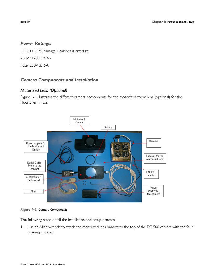
page 10 Chapter 1: Introduction and Setup FluorChem HD2 and FC2 User Guide Power Ratings: DE 500FC MultiImage II cabinet is rated at: 250V 50/60 Hz 3A Fuse: 250V 3.15A Camera Components and Installation Motorized Lens (Optional) Figure 1-4 illustrates the different camera components for the motorized zoom lens (optional) for the FluorChem HD2. Figure 1-4: Camera Components The following steps detail the installation and setup process: 1. Use an Allen wrench to attach the motorized lens bracket to the top of the DE-500 cabinet with the four screws provided