Chapter 4 Running System Section 2 Frame 2.2 Half-beam Frame Good rigidity, Facilitate to maintain engine. Figure 4-9 Half-beam frame 2.3 Beamless Frame 1.Front frame 2.Longeron 3.Clutch housing 4.Transmission and rear-axle housing Saving metal; Good rigidity; High demanding of manufacturing technology and mounting technique; Dismounting Figure 4-10 Beamless frame inconvenient. 1.Engine case 2.Transmission housing 3.Rear-axle housing 机械电子工程学度 Automobile and Tractor Northwest A&F University
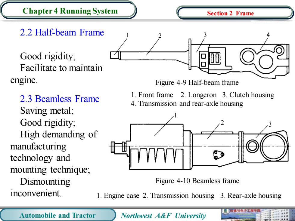
Automobile and Tractor Northwest A&F University Chapter 4 Running System 2.2 Half-beam Frame Good rigidity; Facilitate to maintain engine. 2.3 Beamless Frame Saving metal; Good rigidity; High demanding of manufacturing technology and mounting technique; Dismounting inconvenient. Figure 4-9 Half-beam frame 1. Front frame 2. Longeron 3. Clutch housing 4. Transmission and rear-axle housing 1. Engine case 2. Transmission housing 3. Rear-axle housing Figure 4-10 Beamless frame Section 2 Frame
Chapter 4 Running System Section 3 Axle 1.Front Axle The front axle is to bear the weight of the front parts of automobiles and tractors,and transmits the driving force coming from the frame to the front wheels. Besides,it deflects the wheels a certain angle using steering devices to realize the steering. Figure 4-11 Steering axle 1.1 Automotives'Front Axles 1.Wheel hub 2.Knuckle 3.Centre (1)Front shaft pin 4.Fist part of front shaft 5.Set (2)Knuckle screw wheel angle 6.Thrust bearing 7.Drag link arm 8.Tie rod 9.Front (3)Wheel hub shaft 10.Leaf saddle 机械与电子工程学限 Automobile and Tractor Northwest A&F University
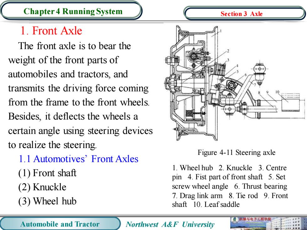
Automobile and Tractor Northwest A&F University Chapter 4 Running System 1. Front Axle The front axle is to bear the weight of the front parts of automobiles and tractors, and transmits the driving force coming from the frame to the front wheels. Besides, it deflects the wheels a certain angle using steering devices to realize the steering. 1.1 Automotives’ Front Axles (1) Front shaft (2) Knuckle (3) Wheel hub Figure 4-11 Steering axle 1. Wheel hub 2. Knuckle 3. Centre pin 4. Fist part of front shaft 5. Set screw wheel angle 6. Thrust bearing 7. Drag link arm 8. Tie rod 9. Front shaft 10. Leaf saddle Section 3 Axle
Chapter 4 Running System Section 3 Axle 1.2 Wheeled Tractors'Front Axles Wheeled tractors'front axles are divided into dual front wheels parted type,dual front wheels collocated type and single front wheel type. (a b (c) Figure 4-12 Front axles of wheeled tractors (a)Dual front wheels parted type (b)Dual front wheels collocated type (c)Single front wheel type 业机械电子工程学 Automobile and Tractor Northwest A&F University
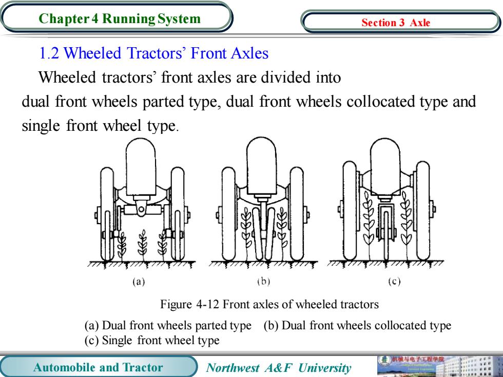
Automobile and Tractor Northwest A&F University Chapter 4 Running System 1.2 Wheeled Tractors’ Front Axles Wheeled tractors’ front axles are divided into dual front wheels parted type, dual front wheels collocated type and single front wheel type. Figure 4-12 Front axles of wheeled tractors (a) Dual front wheels parted type (b) Dual front wheels collocated type (c) Single front wheel type Section 3 Axle
Chapter 4 Running System Section 3 Axle 的 20 19 14 12 13 Figure 4-13 Structures of tractors'front axles 1.Pendulum shaft 2.Bracket 3.Bolt 4.Knuckle arm 5.Deputy sleeve 6.Main stub pin 7.Centre pin 8.Grease seal 9.Knuckle spindle 10.Backing ring 11.Taper roller bearing 12.Front wheel hub 13.Wheel bolt front 14.Paper washer 15.Bearing cap 16.Cotter pin 17.Screw nut 18.Filler ring 19.Taper roller bearing 20.Shaft collar 21.Main collar 22.Pendulum supporting tube 机被与电子工程原 Automobile and Tractor Northwest A&F University
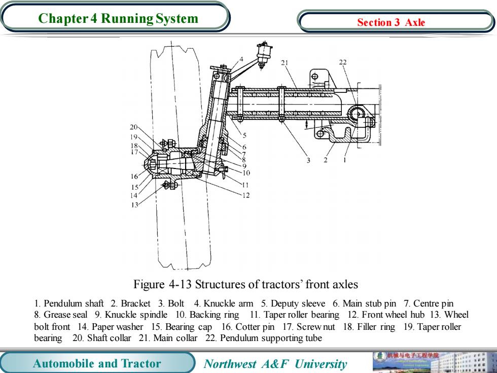
Automobile and Tractor Northwest A&F University Chapter 4 Running System Figure 4-13 Structures of tractors’ front axles 1. Pendulum shaft 2. Bracket 3. Bolt 4. Knuckle arm 5. Deputy sleeve 6. Main stub pin 7. Centre pin 8. Grease seal 9. Knuckle spindle 10. Backing ring 11. Taper roller bearing 12. Front wheel hub 13. Wheel bolt front 14. Paper washer 15. Bearing cap 16. Cotter pin 17. Screw nut 18. Filler ring 19. Taper roller bearing 20. Shaft collar 21. Main collar 22. Pendulum supporting tube Section 3 Axle

Chapter 4 Running System Section 3 Axle 2.Wheel Alignment In order to ensure the vehicles'stability of straight running,light manipulation and reducing the abrasion of tyres and other parts,it is required the front wheels and the kingpin are installed on the front shaft and kept a certain relative position.This installation is called wheel alignment. 2.1 Functions of Kingpin Inward inclination:making the front wheels self-return, which is conducive to maintaining the stability of straight running and light manipulation. Figure 4-14 Kingpin inward inclination 机械电子工程学度 Automobile and Tractor Northwest A&F University
Automobile and Tractor Northwest A&F University Chapter 4 Running System 2. Wheel Alignment In order to ensure the vehicles’ stability of straight running, light manipulation and reducing the abrasion of tyres and other parts, it is required the front wheels and the kingpin are installed on the front shaft and kept a certain relative position. This installation is called wheel alignment. 2.1 Functions of Kingpin Inward inclination: making the front wheels self-return, which is conducive to maintaining the stability of straight running and light manipulation. Figure 4-14 Kingpin inward inclination Section 3 Axle