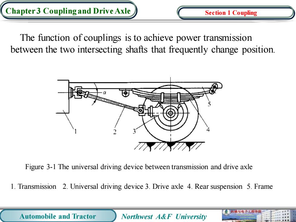
Chapter3 Coupling and Drive Axle Section 1 Coupling The function of couplings is to achieve power transmission between the two intersecting shafts that frequently change position. Figure 3-1 The universal driving device between transmission and drive axle 1.Transmission 2.Universal driving device 3.Drive axle 4.Rear suspension 5.Frame 机械与电子工程度 Automobile and Tractor Northwest A&F University
Automobile and Tractor Northwest A&F University Chapter 3 Coupling and Drive Axle The function of couplings is to achieve power transmission between the two intersecting shafts that frequently change position. Section 1 Coupling Figure 3-1 The universal driving device between transmission and drive axle 1. Transmission 2. Universal driving device 3. Drive axle 4. Rear suspension 5. Frame
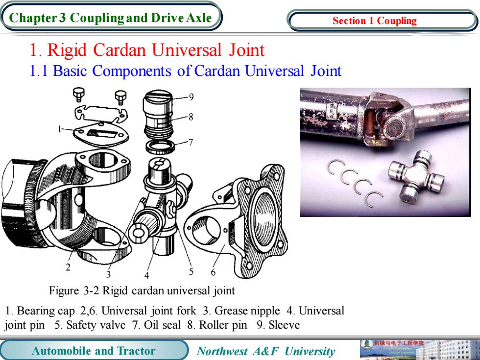
Chapter3 Coupling and Drive Axle Section 1 Coupling 1.Rigid Cardan Universal Joint 1.1 Basic Components of Cardan Universal Joint 甲 甲 9 Figure 3-2 Rigid cardan universal joint 1.Bearing cap 2,6.Universal joint fork 3.Grease nipple 4.Universal joint pin 5.Safety valve 7.Oil seal 8.Roller pin 9.Sleeve 械电子工程学酸 Automobile and Tractor Northwest A&F University
Automobile and Tractor Northwest A&F University Chapter 3 Coupling and Drive Axle 1. Rigid Cardan Universal Joint 1.1 Basic Components of Cardan Universal Joint Figure 3-2 Rigid cardan universal joint 1. Bearing cap 2,6. Universal joint fork 3. Grease nipple 4. Universal joint pin 5. Safety valve 7. Oil seal 8. Roller pin 9. Sleeve Section 1 Coupling

Chapter 3 Coupling and Drive Axle Section 1 Coupling 1.2 The Requirements of Constant Velocity for Double Cardan Universal Joint Figure 3-3 Constant speed drive arrangement of double cardan universal joint 1,3.driving fork 2,4.driven fork 2.Constant Velocity Universal Joint Figure 3-4 Fundamental principle of constant velocity universal joint 机城与电子工程度 Automobile and Tractor Northwest A&F University
Automobile and Tractor Northwest A&F University Chapter 3 Coupling and Drive Axle 1.2 The Requirements of Constant Velocity for Double Cardan Universal Joint 2. Constant Velocity Universal Joint Figure 3-3 Constant speed drive arrangement of double cardan universal joint 1,3. driving fork 2,4. driven fork Figure 3-4 Fundamental principle of constant velocity universal joint Section 1 Coupling
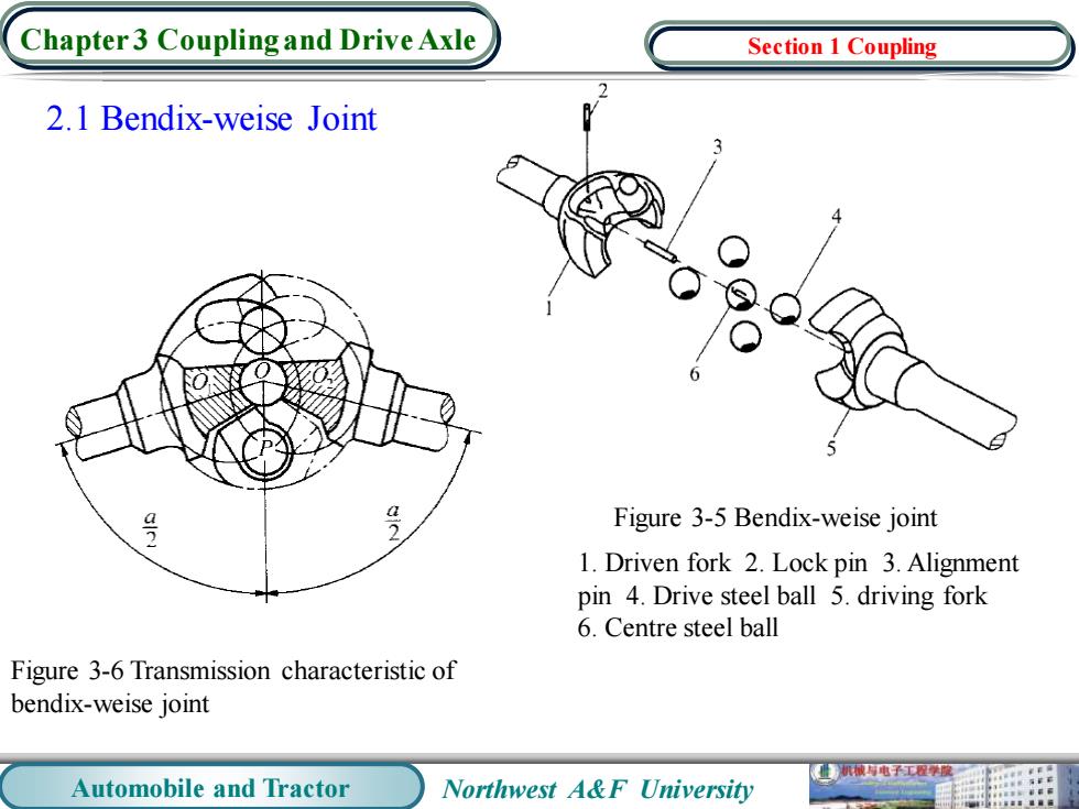
Chapter3 Coupling and Drive Axle Section 1 Coupling 2.1 Bendix-weise Joint 号 Figure 3-5 Bendix-weise joint 1.Driven fork 2.Lock pin 3.Alignment pin 4.Drive steel ball 5.driving fork 6.Centre steel ball Figure 3-6 Transmission characteristic of bendix-weise joint 业机械电子工程学度 Automobile and Tractor Northwest A&F University
Automobile and Tractor Northwest A&F University Chapter 3 Coupling and Drive Axle 2.1 Bendix-weise Joint Figure 3-6 Transmission characteristic of bendix-weise joint Figure 3-5 Bendix-weise joint 1. Driven fork 2. Lock pin 3. Alignment pin 4. Drive steel ball 5. driving fork 6. Centre steel ball Section 1 Coupling
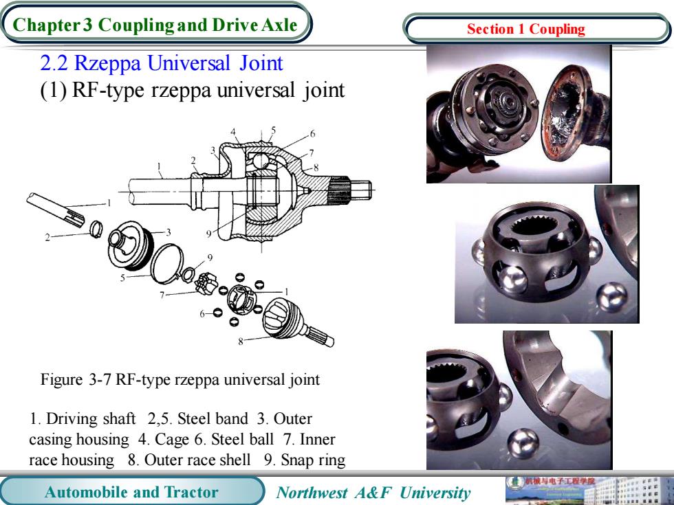
Chapter 3 Coupling and Drive Axle Section 1 Coupling 2.2 Rzeppa Universal Joint (1)RF-type rzeppa universal joint 6● Figure 3-7 RF-type rzeppa universal joint 1.Driving shaft 2,5.Steel band 3.Outer casing housing 4.Cage 6.Steel ball 7.Inner race housing 8.Outer race shell 9.Snap ring 机械与电子工容学聚 Automobile and Tractor Northwest A&F University
Automobile and Tractor Northwest A&F University Chapter 3 Coupling and Drive Axle 2.2 Rzeppa Universal Joint (1) RF-type rzeppa universal joint Figure 3-7 RF-type rzeppa universal joint 1. Driving shaft 2,5. Steel band 3. Outer casing housing 4. Cage 6. Steel ball 7. Inner race housing 8. Outer race shell 9. Snap ring Section 1 Coupling