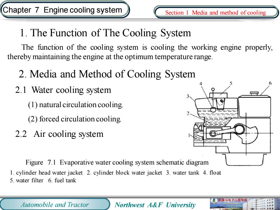
Chapter 7 Engine cooling system Section I Media and method of cooling 1.The Function of The Cooling System The function of the cooling system is cooling the working engine properly, thereby maintaining the engine at the optimum temperature range 2.Media and Method of Cooling System 2.1 Water cooling system (1)natural circulation cooling. (2)forced circulation cooling. 2.2 Air cooling system Figure 7.1 Evaporative water cooling system schematic diagram 1.cylinder head water jacket 2.cylinder block water jacket 3.water tank 4.float 5.water filter 6.fuel tank Automobile and Tractor Northwest A&F University
Automobile and Tractor Northwest A&F University Chapter 7 Engine cooling system 1. The Function of The Cooling System The function of the cooling system is cooling the working engine properly, therebymaintaining the engine at the optimum temperature range. 2. Media and Method of Cooling System 2.1 Water cooling system (1) natural circulation cooling. (2) forced circulation cooling. 2.2 Air cooling system Section 1 Media and method of cooling Figure 7.1 Evaporative water cooling system schematic diagram 1. cylinder head water jacket 2. cylinder block water jacket 3. water tank 4. float 5. water filter 6. fuel tank
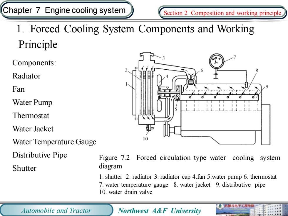
Chapter 7 Engine cooling system Section 2 Composition and working principle 1.Forced Cooling System Components and Working Principle Components: Radiator Fan Water Pump Thermostat Water Jacket Water Temperature Gauge 10 Distributive Pipe Figure 7.2 Forced circulation type water cooling system Shutter diagram 1.shutter 2.radiator 3.radiator cap 4.fan 5.water pump 6.thermostat 7.water temperature gauge 8.water jacket 9.distributive pipe 10.water drain valve 械电子工程学酸 Automobile and Tractor Northwest A&F University
Automobile and Tractor Northwest A&F University Chapter 7 Engine cooling system 1. Forced Cooling System Components and Working Principle Components : Radiator Fan Water Pump Thermostat Water Jacket Water Temperature Gauge Distributive Pipe Shutter Figure 7.2 Forced circulation type water cooling system diagram 1. shutter 2. radiator 3. radiator cap 4.fan 5.water pump 6. thermostat 7. water temperature gauge 8. water jacket 9. distributive pipe 10. water drain valve Section 2 Composition and working principle
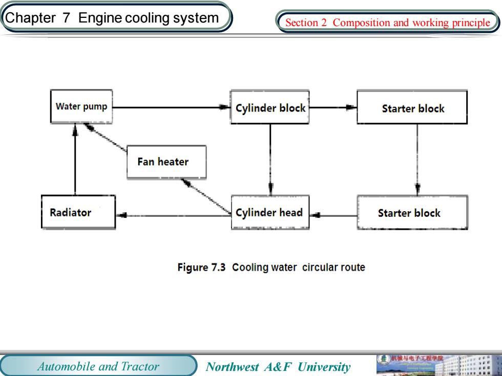
Chapter 7 Engine cooling system Section 2 Composition and working principle Water pump Cylinder block Starter block Fan heater Radiator Cylinder head Starter block Figure 7.3 Cooling water circular route 机械与电子工程学模二 Automobile and Tractor Northwest A&F University
Automobile and Tractor Northwest A&F University Chapter 7 Engine cooling system Section 2 Composition and working principle
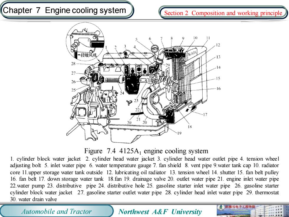
Chapter 7 Engine cooling system Section 2 Composition and working principle 东 Figure 7.4 4125A engine cooling system 1.cylinder block water jacket 2.cylinder head water jacket 3.cylinder head water outlet pipe 4.tension wheel adjusting bolt 5.inlet water pipe 6.water temperature gauge 7.fan shield 8.vent pipe 9.water tank cap 10.radiator core 11.upper storage water tank outside 12.lubricating oil radiator 13.tension wheel 14.shutter 15.fan belt pulley 16.fan belt 17.down storage water tank 18.fan 19.drainage valve 20.outlet water pipe 21.engine inlet water pipe 22.water pump 23.distributive pipe 24.distributive hole 25.gasoline starter inlet water pipe 26.gasoline starter cylinder block water jacket 27.gasoline starter outlet water pipe 28.cylinder head inlet water pipe 29.thermostat 30.water drain valve 业机电子工程学度 Automobile and Tractor Northwest A&F University
Automobile and Tractor Northwest A&F University Chapter 7 Engine cooling system Figure 7.4 4125A1 engine cooling system 1. cylinder block water jacket 2. cylinder head water jacket 3. cylinder head water outlet pipe 4. tension wheel adjusting bolt 5. inlet water pipe 6. water temperature gauge 7. fan shield 8. vent pipe 9.water tank cap 10. radiator core 11.upper storage water tank outside 12. lubricating oil radiator 13. tension wheel 14. shutter 15. fan belt pulley 16. fan belt 17. down storage water tank 18.fan 19. drainage valve 20. outlet water pipe 21. engine inlet water pipe 22.water pump 23. distributive pipe 24. distributive hole 25. gasoline starter inlet water pipe 26. gasoline starter cylinder block water jacket 27. gasoline starter outlet water pipe 28. cylinder head inlet water pipe 29. thermostat 30. water drain valve Section 2 Composition and working principle
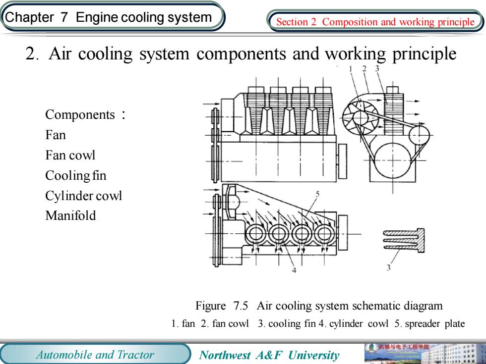
Chapter 7 Engine cooling system Section 2 Composition and working principle 2.Air cooling system components and working principle Components Fan Fan cowl Cooling fin Cylinder cowl Manifold Figure 7.5 Air cooling system schematic diagram 1.fan 2.fan cowl 3.cooling fin 4.cylinder cowl 5.spreader plate 机被电子工程学度 Automobile and Tractor Northwest A&F University
Automobile and Tractor Northwest A&F University Chapter 7 Engine cooling system 2. Air cooling system components and working principle Components : Fan Fan cowl Cooling fin Cylinder cowl Manifold Figure 7.5 Air cooling system schematic diagram 1. fan 2. fan cowl 3. cooling fin 4. cylinder cowl 5. spreader plate Section 2 Composition and working principle