Chapter 2 Transmission Section 1 Introduction 1.Functions of Transmissions (1)Change the speed and torque; (2)Achieve forward or backward for vehicles; (3)Achieve a long time stop or power output; (4)Achieve the start or idle for the vehicle in off-load conditions. 2.Types of Transmissions 2.1 Transmission Ratio According to different transmission ratio settings,transmissions are divided into mechanical transmission,continuously variable transmission and integrated transmission. (1)Mechanical transmissions have several transmission ratios. They transmit power by gear trains. 机械与电子工程家 Automobile and Tractor Northwest A&F University
Automobile and Tractor Northwest A&F University Chapter 2 Transmission 1. Functions of Transmissions (l) Change the speed and torque; (2) Achieve forward or backward for vehicles; (3) Achieve a long time stop or power output; (4) Achieve the start or idle for the vehicle in off-load conditions. 2. Types of Transmissions 2.1 Transmission Ratio According to different transmission ratio settings, transmissions are divided into mechanical transmission, continuously variable transmission and integrated transmission. (1) Mechanical transmissions have several transmission ratios. They transmit power by gear trains. Section 1 Introduction
Chapter 2 Transmission Section 1 Introduction According to the structures of gear trains,transmissions can be divided into ordinary transmissions(axis fixed)and planetary transmissions(axis rotated).According to whether the power transfer is interrupted in transmission process,transmissions are divided into traditional transmissions and loaded shift transmissions. (2)Transmission ratios of continuously variable transmission can be continuously variable within a certain range.Usually they can be divided into hydraulic transmissions and electrical transmissions. (3)Integrated transmissions are composed by a mechanical transmission and a stepless hydraulic torque converter.They are also known as the hydraulic mechanical transmissions.The transmission ratios of them are continuously variable within a number of intervals. 状械电子工程学 Automobile and Tractor Northwest A&F University
Automobile and Tractor Northwest A&F University Chapter 2 Transmission According to the structures of gear trains, transmissions can be divided into ordinary transmissions(axis fixed) and planetary transmissions(axis rotated). According to whether the power transfer is interrupted in transmission process, transmissions are divided into traditional transmissions and loaded shift transmissions. (2) Transmission ratios of continuously variable transmission can be continuously variable within a certain range. Usually they can be divided into hydraulic transmissions and electrical transmissions. (3) Integrated transmissions are composed by a mechanical transmission and a stepless hydraulic torque converter. They are also known as the hydraulic mechanical transmissions. The transmission ratios of them are continuously variable within a number of intervals. Section 1 Introduction
Chapter 2 Transmission Section 1 Introduction 2.2 Operation Manner According to operation manners,transmissions are divided into three types:manual,automatic and semi-automatic. (1)Manual transmissions rely on drivers direct control of the gear lever to shift. (2)Automatic transmissions rely on drivers control of the accelerator pedal to control the speed. (3)Semi-automatic transmissions can be divided into two forms: one is that several commonly used gears are in automatic control, while other gears are manipulated by the driver;The other is that the driver sets the required gears forward with the button,and then achieve to shift through the accelerator pedal to connect the electromagnetic device or hydraulic device. 机械电子工程学理 Automobile and Tractor Northwest A&F University
Automobile and Tractor Northwest A&F University Chapter 2 Transmission 2.2 Operation Manner According to operation manners, transmissions are divided into three types: manual, automatic and semi-automatic. (1)Manual transmissions rely on drivers direct control of the gear lever to shift. (2)Automatic transmissions rely on drivers control of the accelerator pedal to control the speed. (3) Semi-automatic transmissions can be divided into two forms: one is that several commonly used gears are in automatic control, while other gears are manipulated by the driver; The other is that the driver sets the required gears forward with the button, and then achieve to shift through the accelerator pedal to connect the electromagnetic device or hydraulic device. Section 1 Introduction
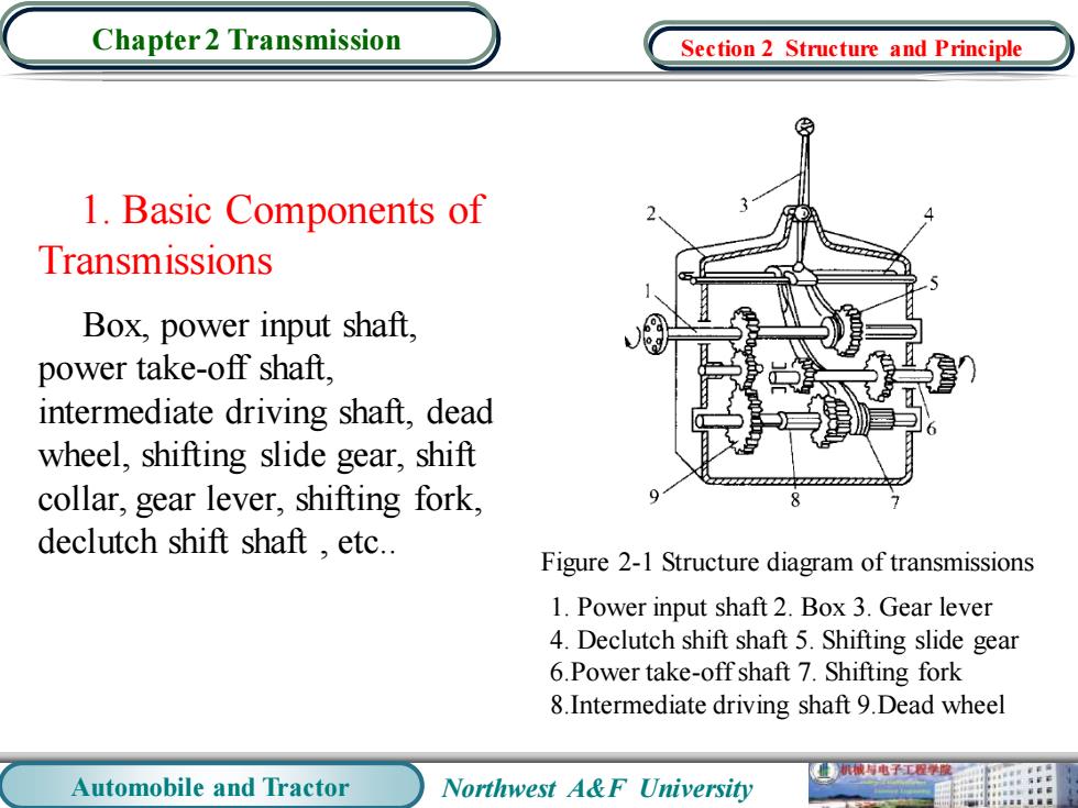
Chapter 2 Transmission Section 2 Structure and Principle 1.Basic Components of Transmissions Box,power input shaft, power take-off shaft. intermediate driving shaft,dead wheel,shifting slide gear,shift collar,gear lever,shifting fork, declutch shift shaft,etc.. Figure 2-1 Structure diagram of transmissions 1.Power input shaft 2.Box 3.Gear lever 4.Declutch shift shaft 5.Shifting slide gear 6.Power take-off shaft 7.Shifting fork 8.Intermediate driving shaft 9.Dead wheel 械电子工程学 Automobile and Tractor Northwest A&F University
Automobile and Tractor Northwest A&F University Chapter 2 Transmission 1. Basic Components of Transmissions Box, power input shaft, power take-off shaft, intermediate driving shaft, dead wheel, shifting slide gear, shift collar, gear lever, shifting fork, declutch shift shaft , etc.. 1. Power input shaft 2. Box 3. Gear lever 4. Declutch shift shaft 5. Shifting slide gear 6.Power take-off shaft 7. Shifting fork 8.Intermediate driving shaft 9.Dead wheel Figure 2-1 Structure diagram of transmissions Section 2 Structure and Principle
Chapter 2 Transmission Section 2 Structure and Principle 2.The Types and Working Principles of Transmissions 2.1 Twin-shaft Transmission 10 13 不 29 28/26/24 27252322 2120/18/16 1917 Figure 2-2 Transmission driving mechanism diagram of Audi 100 automobiles 1.Power input shaft 2.Power take-off shaft 2,3,4,9,10.Driving gears of I,II,III,IV V gear respectively 11,13. Driving gear and driven gear ofreverse gear 14.Shaft reverse idler gear 15.Reverse idler gear 28,23,22,21,20. Driven gears of I,II,III,IV V gear respectively ,8,16,19,24,27.Lock rings of synchronizers 7,18,26.Spline hubs of synchronizers 6,17,25.Synchromesh sliding sleeve 29.Driving bevel gear of final drive 机被有电子工学度 Automobile and Tractor Northwest A&F University 用
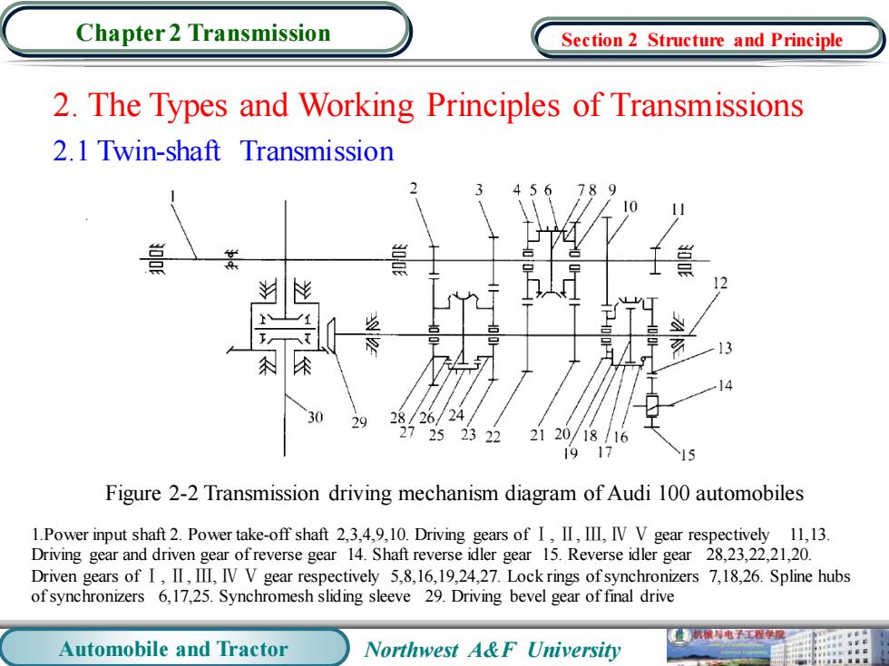
Automobile and Tractor Northwest A&F University Chapter 2 Transmission 2. The Types and Working Principles of Transmissions 2.1 Twin-shaft Transmission Figure 2-2 Transmission driving mechanism diagram of Audi 100 automobiles 1.Power input shaft 2. Power take-off shaft 2,3,4,9,10. Driving gears of Ⅰ, Ⅱ, Ⅲ, Ⅳ Ⅴ gear respectively 11,13. Driving gear and driven gear of reverse gear 14. Shaft reverse idler gear 15. Reverse idler gear 28,23,22,21,20. Driven gears of Ⅰ, Ⅱ, Ⅲ, Ⅳ Ⅴ gear respectively 5,8,16,19,24,27. Lock rings of synchronizers 7,18,26. Spline hubs of synchronizers 6,17,25. Synchromesh sliding sleeve 29. Driving bevel gear of final drive Section 2 Structure and Principle