apart.Since the electric field strength in the region between the plates is given by E=o/,the external force can be rewritten as F. (5.3.5) 2 The external force F is independent of d.The total amount of work done externally to separate the plates by a distance d is then 形=∫Es=rd=E4d 2Γ (5.3.6) consistent with Eq.(5.3.3).Because the potential energy of the system is equal to the work done by the external agent,we have that the energy density u=W/Ad=E2/2 In addition,we note that the expression for ug is identical to Eq.(3.4.8)in Chapter 3. Therefore,the electric energy density ug can also be interpreted as electrostatic pressure P Example 5.4:Electric Energy Density of Dry Air The breakdown field strength at which dry air loses its insulating ability and allows a discharge to pass through is E=3x10V/m.At this field strength,the electric energy density is: Nm3x 10*V/m)40 Jm 1 (5.3.7) Example 5.5:Energy Stored in a Spherical Shell Find the energy stored in a metallic spherical shell of radius a and charge O. Solution:The electric field associated of a spherical shell of radius a is(Example 3.3) r,r>a E- (5.3.8) 0, r<a. The corresponding energy density is 1 eE2= 03 4E= 2 (5.3.9) 32π2er4 5-11
5-11 apart. Since the electric field strength in the region between the plates is given by 0 E = ! / " , the external force can be rewritten as 0 2 ext 2 F E A ! = . (5.3.5) The external force Fext is independent of d . The total amount of work done externally to separate the plates by a distance d is then 2 0 ext ext ext 2 E A W d F d d " ! # = $ = = % & ' ( ) F s ! ! , (5.3.6) consistent with Eq. (5.3.3). Because the potential energy of the system is equal to the work done by the external agent, we have that the energy density 2 ext 0 / / 2 E u =W Ad = ! E . In addition, we note that the expression for E u is identical to Eq. (3.4.8) in Chapter 3. Therefore, the electric energy density E u can also be interpreted as electrostatic pressure P. Example 5.4: Electric Energy Density of Dry Air The breakdown field strength at which dry air loses its insulating ability and allows a discharge to pass through is 6 Eb = 3!10 V/m . At this field strength, the electric energy density is: uE = 1 2 ! 0E2 = 1 2 (8.85 " 10-12 C2 /N #m2 )(3" 106 V/m) 2 = 40 J/m3 . (5.3.7) Example 5.5: Energy Stored in a Spherical Shell Find the energy stored in a metallic spherical shell of radius a and charge Q. Solution: The electric field associated of a spherical shell of radius a is (Example 3.3) E !" = Q 4!" 0 r 2 rˆ, r > a " 0, r < a. # $ % & % (5.3.8) The corresponding energy density is 2 2 0 2 4 0 1 2 32 E Q u E r ! " ! = = , (5.3.9)
outside the sphere,and zero inside.Since the electric field is non-vanishing outside the spherical shell,we must integrate over the entire region of space from r=a to r=.In spherical coordinates,with dy=4ur'dr,we have (5.3.10) where /=O/4ea is the electric potential on the surface of the shell,with V()=0. We can readily verify that the energy of the system is equal to the work done in charging the sphere.To show this,suppose at some instant the sphere has charge g and is at a potential V=g/4a.The work required to add an additional charge dg to the system is dw =Vdg.Thus,the total work is W-Sdw-Svdq-S'dq 9 o" 4πea (5.3.11) 8πeoa 5.4 Dielectrics In many capacitors there is an insulating material such as paper or plastic between the plates.Such material,called a dielectric,can be used to maintain a physical separation of the plates.Since dielectrics break down less readily than air,charge leakage can be minimized,especially when high voltage is applied. Experimentally it was found that capacitance C increases when the space between the conductors is filled with dielectrics.To see how this happens,suppose a capacitor has a capacitance Co when there is no material between the plates.When a dielectric material is inserted to completely fill the space between the plates,the capacitance increases to C=KCo, (5.4.1) where K.is called the dielectric constant.In the Table below,we show some dielectric materials with their dielectric constant.Experiments indicate that all dielectric materials have K.>1.Note that every dielectric material has a characteristic dielectric strength that is the maximum value of electric field before breakdown occurs and charges begin to flow. 5-12
5-12 outside the sphere, and zero inside. Since the electric field is non-vanishing outside the spherical shell, we must integrate over the entire region of space from r = a to r = ! . In spherical coordinates, with 2 dV = 4! r dr , we have 2 2 2 2 2 4 2 0 0 0 1 4 32 8 8 2 E a a Q Q dr Q U r dr QV r r a ! ! " !" !" # $ % # = & ' = = = ( ) * * , (5.3.10) where 0 V = Q / 4!" a is the electric potential on the surface of the shell, with V (!) = 0 . We can readily verify that the energy of the system is equal to the work done in charging the sphere. To show this, suppose at some instant the sphere has charge q and is at a potential 0 V = q / 4!" a . The work required to add an additional charge dq to the system is dW =Vdq . Thus, the total work is 2 0 0 0 4 8 Q q Q W dW Vdq dq !" a !" a # $ = = = % & = ' ( ) ) ) . (5.3.11) 5.4 Dielectrics In many capacitors there is an insulating material such as paper or plastic between the plates. Such material, called a dielectric, can be used to maintain a physical separation of the plates. Since dielectrics break down less readily than air, charge leakage can be minimized, especially when high voltage is applied. Experimentally it was found that capacitance C increases when the space between the conductors is filled with dielectrics. To see how this happens, suppose a capacitor has a capacitance C0 when there is no material between the plates. When a dielectric material is inserted to completely fill the space between the plates, the capacitance increases to C = !eC0 , (5.4.1) where !e is called the dielectric constant. In the Table below, we show some dielectric materials with their dielectric constant. Experiments indicate that all dielectric materials have 1 !e > . Note that every dielectric material has a characteristic dielectric strength that is the maximum value of electric field before breakdown occurs and charges begin to flow
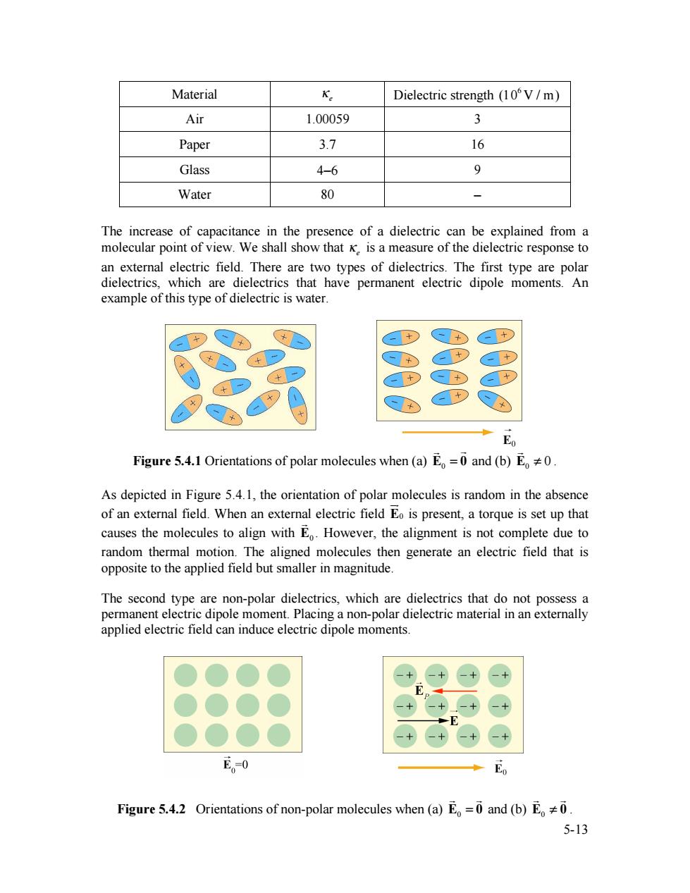
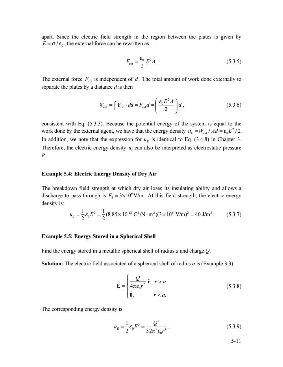
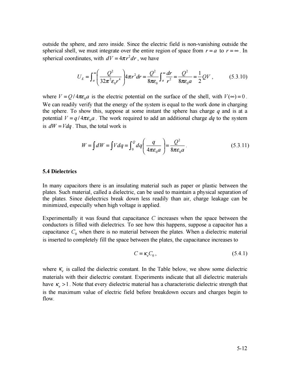
Material K Dielectric strength (10V/m) Air 1.00059 3 Paper 3.7 16 Glass 4-6 9 Water 80 - The increase of capacitance in the presence of a dielectric can be explained from a molecular point of view.We shall show that K.is a measure of the dielectric response to an external electric field.There are two types of dielectrics.The first type are polar dielectrics,which are dielectrics that have permanent electric dipole moments.An example of this type of dielectric is water. Eo Figure 5.4.1 Orientations of polar molecules when (a)E=0 and (b)E0. As depicted in Figure 5.4.1,the orientation of polar molecules is random in the absence of an external field.When an external electric field Eo is present,a torque is set up that causes the molecules to align with E.However,the alignment is not complete due to random thermal motion.The aligned molecules then generate an electric field that is opposite to the applied field but smaller in magnitude. The second type are non-polar dielectrics,which are dielectrics that do not possess a permanent electric dipole moment.Placing a non-polar dielectric material in an externally applied electric field can induce electric dipole moments. E。0 E Figure 5.4.2 Orientations of non-polar molecules when (a)E=0 and (b)E0 5-13
5-13 Material !e Dielectric strength (106 V / m) Air 1.00059 3 Paper 3.7 16 Glass 4−6 9 Water 80 − The increase of capacitance in the presence of a dielectric can be explained from a molecular point of view. We shall show that !e is a measure of the dielectric response to an external electric field. There are two types of dielectrics. The first type are polar dielectrics, which are dielectrics that have permanent electric dipole moments. An example of this type of dielectric is water. Figure 5.4.1 Orientations of polar molecules when (a) E0 = 0 ! ! and (b) 0 E ! 0 ! . As depicted in Figure 5.4.1, the orientation of polar molecules is random in the absence of an external field. When an external electric field E0 !" is present, a torque is set up that causes the molecules to align with E0 ! . However, the alignment is not complete due to random thermal motion. The aligned molecules then generate an electric field that is opposite to the applied field but smaller in magnitude. The second type are non-polar dielectrics, which are dielectrics that do not possess a permanent electric dipole moment. Placing a non-polar dielectric material in an externally applied electric field can induce electric dipole moments. Figure 5.4.2 Orientations of non-polar molecules when (a) E0 = 0 ! ! and (b) E0 ! 0 ! !