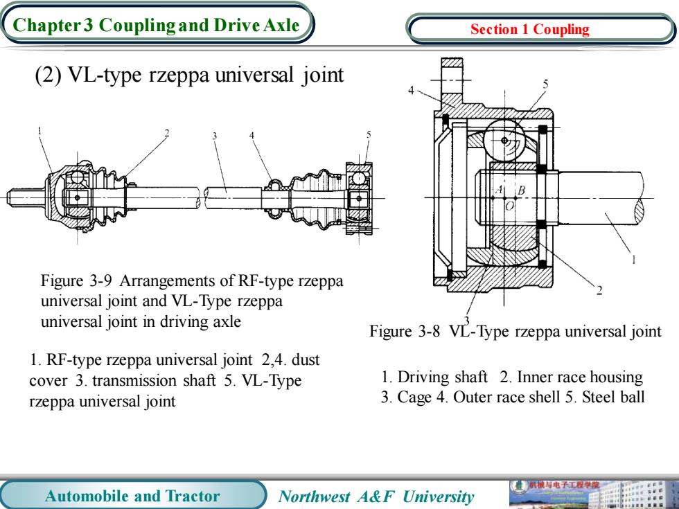
Chapter 3 Coupling and Drive Axle Section 1 Coupling (2)VL-type rzeppa universal joint B Figure 3-9 Arrangements of RF-type rzeppa universal joint and VL-Type rzeppa universal joint in driving axle Figure 3-8 VL-Type rzeppa universal joint 1.RF-type rzeppa universal joint 2,4.dust cover 3.transmission shaft 5.VL-Type 1.Driving shaft 2.Inner race housing rzeppa universal joint 3.Cage 4.Outer race shell 5.Steel ball 业机械电子工程学 Automobile and Tractor Northwest A&F University
Automobile and Tractor Northwest A&F University Chapter 3 Coupling and Drive Axle (2) VL-type rzeppa universal joint 1. Driving shaft 2. Inner race housing 3. Cage 4. Outer race shell 5. Steel ball Figure 3-8 VL-Type rzeppa universal joint Figure 3-9 Arrangements of RF-type rzeppa universal joint and VL-Type rzeppa universal joint in driving axle 1. RF-type rzeppa universal joint 2,4. dust cover 3. transmission shaft 5. VL-Type rzeppa universal joint Section 1 Coupling
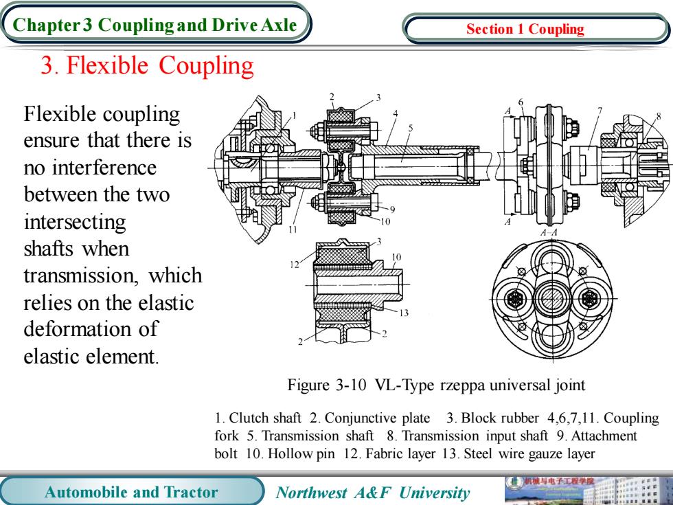
Chapter3 Coupling and Drive Axle Section 1 Coupling 3.Flexible Coupling Flexible coupling ensure that there is no interference between the two intersecting shafts when transmission,which relies on the elastic deformation of elastic element. Figure 3-10 VL-Type rzeppa universal joint 1.Clutch shaft 2.Conjunctive plate 3.Block rubber 4,6,7,11.Coupling fork 5.Transmission shaft 8.Transmission input shaft 9.Attachment bolt 10.Hollow pin 12.Fabric layer 13.Steel wire gauze layer 机被有电子工程学原 Automobile and Tractor Northwest A&F University
Automobile and Tractor Northwest A&F University Chapter 3 Coupling and Drive Axle 3. Flexible Coupling Flexible coupling ensure that there is no interference between the two intersecting shafts when transmission, which relies on the elastic deformation of elastic element. Figure 3-10 VL-Type rzeppa universal joint 1. Clutch shaft 2. Conjunctive plate 3. Block rubber 4,6,7,11. Coupling fork 5. Transmission shaft 8. Transmission input shaft 9. Attachment bolt 10. Hollow pin 12. Fabric layer 13. Steel wire gauze layer Section 1 Coupling