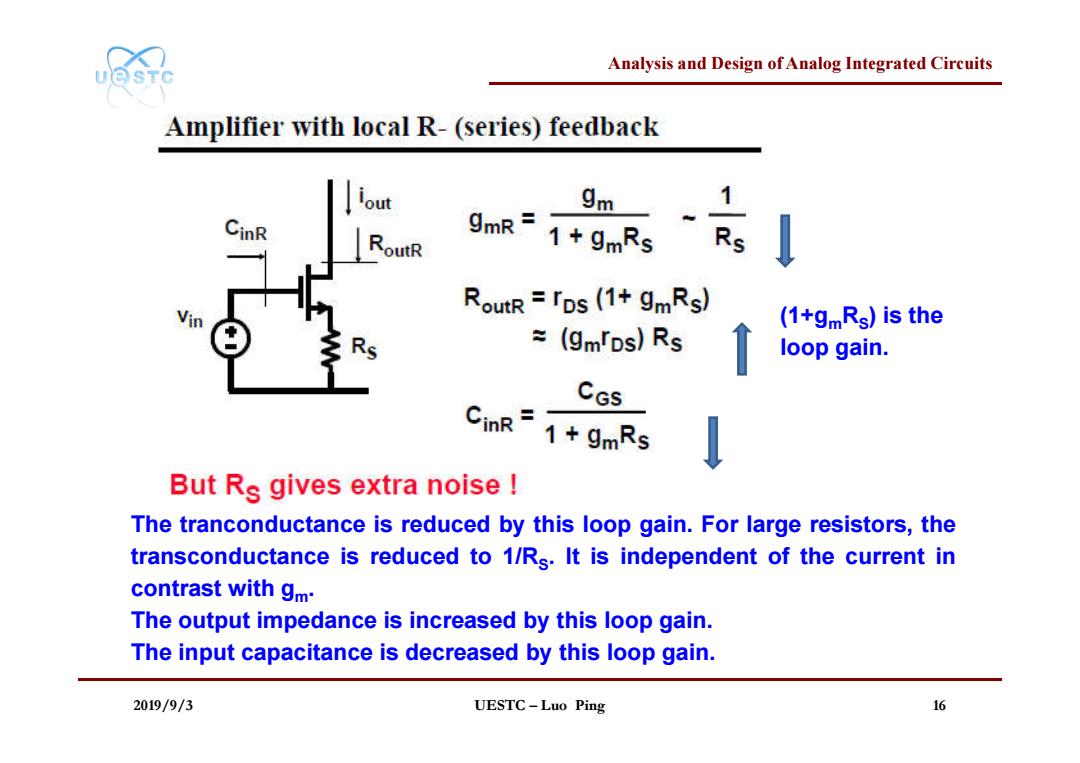
Analysis and Design of Analog Integrated Circuits UQSTC Amplifier with local R-(series)feedback out 9m 1 RoutR 1+gmRs Rs RoutR rps (1+gmRs) (1+gmRs)is the ¥(gmps)Rs loop gain. CGs 1+gmRs But Rs gives extra noise The tranconductance is reduced by this loop gain.For large resistors,the transconductance is reduced to 1/Rs.It is independent of the current in contrast with gm. The output impedance is increased by this loop gain. The input capacitance is decreased by this loop gain. 2019/9/3 UESTC-Luo Ping 16
Analysis and Design of Analog Integrated Circuits 2019/9/3 UESTC – Luo Ping 16 (1+gmRS) is the loop gain. The tranconductance is reduced by this loop gain. For large resistors, the transconductance is reduced to 1/RS. It is independent of the current in contrast with gm. The output impedance is increased by this loop gain. The input capacitance is decreased by this loop gain

Analysis and Design of Analog Integrated Circuits UQSTC Amplifier with local L-feedback 9mR= 9m1 1+gmRs Rs 9m RoutR rps (1+gmRs) 1+gmLss ÷(gmTDs)Rs RoutL rps (1+gmLss) Ls+1+LsCGss2 ZinL=9m CGs s CGs Ziml.=Zin[1+gmLs] No extra noise! Inductances and capacitances do not give noise,at least not as long as their series loss resistance is zero. 2019/9/3 UESTC-Luo Ping 17
Analysis and Design of Analog Integrated Circuits 2019/9/3 UESTC – Luo Ping 17 X Inductances and capacitances do not give noise, at least not as long as their series loss resistance is zero. [1 ] Z Z g L s inL in m s
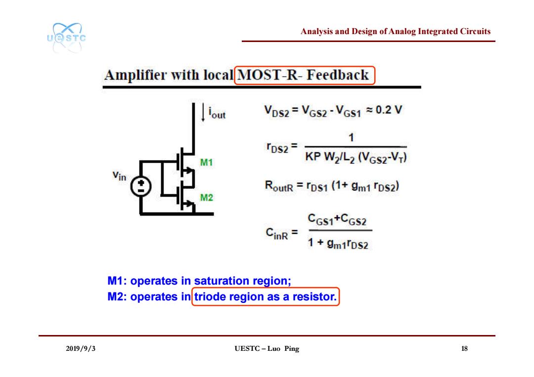
Analysis and Design of Analog Integrated Circuits UOSTC Amplifier with localMOST-R-Feedback iout VDs2=VGS2-VGS1 =0.2 V 1 r0s2= M1 KP W2/L2 (VGS2-V-) RoutR rDs1(1+gm1 rps2) CGS1+CGS2 CinR= 1+gm1TDS2 M1:operates in saturation region; M2:operates intriode region as a resistor. 2019/9/3 UESTC-Luo Ping 18
Analysis and Design of Analog Integrated Circuits 2019/9/3 UESTC – Luo Ping 18 M1: operates in saturation region; M2: operates in triode region as a resistor

Analysis and Design of Analog Integrated Circuits UQSTC Diode-connected MOST parallel Feedback Vos=VGS-VT Vos=VGS I-V curve of diode VDs VGS VGs safuration G=D ls=Kn光(Vps-V:)2 0 Vps ips convert current to voltage VGS 「ds=1/gm∥rps=1/gm rDs 9mVGS 2019/9/3 UESTC-Luo Ping 19
Analysis and Design of Analog Integrated Circuits 2019/9/3 UESTC – Luo Ping 19 I-V curve of diode convert current to voltage

Analysis and Design of Analog Integrated Circuits UQSTC Diode-connected MOST at high frequencies rds=1/gm∥rps≈1/gm CGS 9mVGS rDs G=D 9m BW=- (CGs+CDs) 2 CGs~Cps g.=k少亿s-) L High fr,need large(Ves-V-)and minimum channel length L. 2019/9/3 UESTC-Luo Ping 20
Analysis and Design of Analog Integrated Circuits 2019/9/3 UESTC – Luo Ping 20 High fT, need large (VGS-VT) and minimum channel length L. ' ( ) m GS T W g k V V L CGS≈CDS