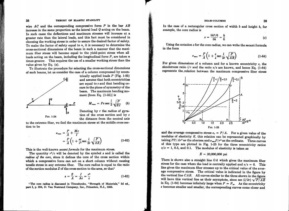
38 THEORY OF ELASTIC STABILITY BEAM-COLUMN8 39 wire AC and the corresponding compressive force P in the bar AB In the case of a rectangular cross section of width b and height h,for increase in the same proportion as the lateral load Q acting on the beam. example,the core radius is In such cases the deflections and maximum stresses will increase at a greater rate than the lateral loads,and this fact must be considered in 。=状-合 bh (d) choosing the working stress in order to assure the desired factor of safety. To make the factor of safety equal to n,it is necessary to determine the Using the notation s for the core radius,we can write the secant formula cross-sectional dimensions of the beam in such a manner that the maxi- in the form mum fiber stress will become equal to the yield-point stress when all loads acting on the beam,including the longitudinal force P,are taken n (1-64) times greater.This requires the use of a smaller working stress than the value given by Eq.(a). For given dimensions of a column and for a known eccentricity e,the To illustrate the procedure for selecting the cross-sectional dimensions slenderness ratio l/r and the ratio e/s are known,and hence Eq.(1-64) of such beams,let us consider the case of a column compressed by eccen- represents the.relation between the maximum compressive fber stress trically applied loads P(Fig.1-86) and assume that both eccentricities 号/-5 are equal to e and that bending oc- m curs in the plane of symmetry of the beam.The maximum bending mo- ment [from Eq.(1-35)]is A 中 M-%i圆 () 2 -0 R Denoting by r the radius of gyra- -m2 F1a,1-24 tion of the cross section and by c the distance from the neutral axis to the extreme fiber,we find the maximum stress at the middle cross sec- 00 051.0152.025 tion to be f0.125 + and the average compressive stress =P/A.For a given value of the modulus of elasticity E,this relation can be represented graphically by = P( P (1-62) taking Pl/Ar as the abscissa and/r*as the ordinate. Three curves of this type are plotted in Fig.1-25 for the three eccentricity ratios This is the well-known secant formula for the maximum stress. e/s=1,0.5,and 0.1.The modulus of elasticity is taken as The quantity r/c will be denoted by the symbol s and is called the E=30,000,000psi radius of the core,since it defines the core of the cross section within which a compressive force can act on a short column without causing There is shown also a straight line OA which gives the maximum fiber tensile stress in any extreme fiber.The core radius is equal to the ratio stress for the case where the load is centrally applied and e/s=0.This of the section modulus Z of the cross section to the area,so that! line gives the maximum fiber stresses up to the critical value of the aver- age compressive stress.The critical value is indicated in the figure by ==元=8 (1-63) the vertical line CAB.All curves similar to the three shown in the figure will have this vertical line as their asymptote,since sec (/2r)VP7AB The core radius is discuseed in Timoshenko,"Strength of Materials,"3d od, in Eq.(1-64)becomes infinitely large when P=P As the eccentricity part I,p.254,D.Van Nostrand Company,Ine.,Princeton,N.J.,1955. e becomes smaller and smaller,the corresponding curves come closer and
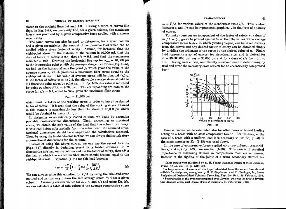
BEAM-COLUMNB 40 THEORY OF ELASTIC 8TABILITY 41 closer to the straight lines 0A and AB.Having a series of curves like .P/A for various values of the slenderness ratio l/r.This relation those in Fig.1-25,we can easily find,for a given column,the maximum between and //r can be represented graphically in the form of a family fiber stress produced by a given compressive foree applied with a known of curves. To make these curves independent of the factor of safety n,values of eccentricity. The same curves can also be used to determine,for a given column nP/A =()rr can be plotted against l/r so that the values of the average and a given eccentricity,the amount of compressive load which can be compressive stress ()at which yielding begins,can be taken directly applied with a given factor of safety.Assume,for instance,that the from the curves and any desired factor of safety can be obtained simply yield-point stress for the material of the column is 40,000 psi,that the by dividing the ordinates of the curve by the desired value of n.Figure desired factor of safety is 2.5,that e/s=0.1,and that the slenderness 1-26 represents a set of curves'for structural steel and is plotted for ratio l/r -100.Drawing the horizontal line mp for=40,000 psi E=30,000,000 psi,vr=36,000 psi and for values of e/s from 0.1 to to the intersection point p with the corresponding curve for e/s(Fig.1-25), 1.0.Having such curves,no difficulty is encountered in determining by we find on the horizontal axis the point pi which gives the value of the trial and error the necessary crogs section for an eccentrically compressed bar. average stress o which produces a maximum fiber stress equal to the yield-point stress.This value of average stress will be denoted () 36r3-01 If the factor of safety is to be 2.5,the allowable average stress should be 32F 0.4 times the value given by point p.In Fig.1-25 this value is indicated 2 31.0 by point pa where P/A =9,700 psi.The corresponding ordinate to the 28上 244 curve for e/s=0.1,equal to Oma,gives the maximum fiber stress -000 m=11,400 psi 三18 which must be taken as the working stress in order to have the desired 12 factor of safety.It is seen that the value of the working stress obtained in this manner is considerably less than the stress of 16,000 psi which would be obtained by using Eq.(a). In designing an eccentrically loaded column,we begin by assuming 40 1a0 60200 probable cross-sectional dimensions.Then,proceeding as explained Values of Slenderness Ratio above,we obtain the safe value of the load that the column can carry. Fre.1-26 If this load differs substantially from the actual load,the assumed cross- sectional dimensions should be changed and the calculations repeated. Similar curves can be caleulated also for other cases of lateral loading Thus,by using the trial-and-error method we can always find satisfactory acting on a beam with an axial compressive foree.For instance,in the case of a beam with a uniform load it is necessary to use Eg.(1-23)in cross-sectional dimensions for the column. Instead of using the above curves,we can use the secant formula the same manner as Eq.(1-35)was used above. [Eq.(1-64)]directly in designing eccentrically loaded columns.If P In the case of compressive forces applied with two different eccentrici- denotes the safe load on the column and n is the factor of safety,then nP is ties ea and es(Fig.1-27),we use Eq.(1-30).This case is of practical the load at which the maximum fiber stress should become equal to the importance in discussing stresses in compression members of trusses. yield-point stress. Equation (1-64)for this load becomes Because of the rigidity of the joints of a truss,secondary stresses are These curves were calculated by D.H.Young,Rational Design of Steel Columns, nP APY (④ Trans.ASCE,vol.101,p.422 1936. A large number of curves of thia type,caleulnted from the secant formula and We can always solve this equation for P/A by using the trial-and-error suitable for design une,were given by H.K.Stephenson and K.Cloninger,Jr,Stress Annlysis and Design of Steel Columnn,Teraa Eng.Bzpt.Sta.Bull.129,February,1953. method and in this way obtain the safe average stress P/A for a given Beveral tables of this type were prepared by 8.Zavriev,who was the first to develop column.Assuming certain values for ove,n,and e/s and using Eq.(d), this ides;see Mem.Inat.Engrs.Ways of Commun.,St.Petersburg,1913. we can calculate a table of safe values of the average compressive gtress
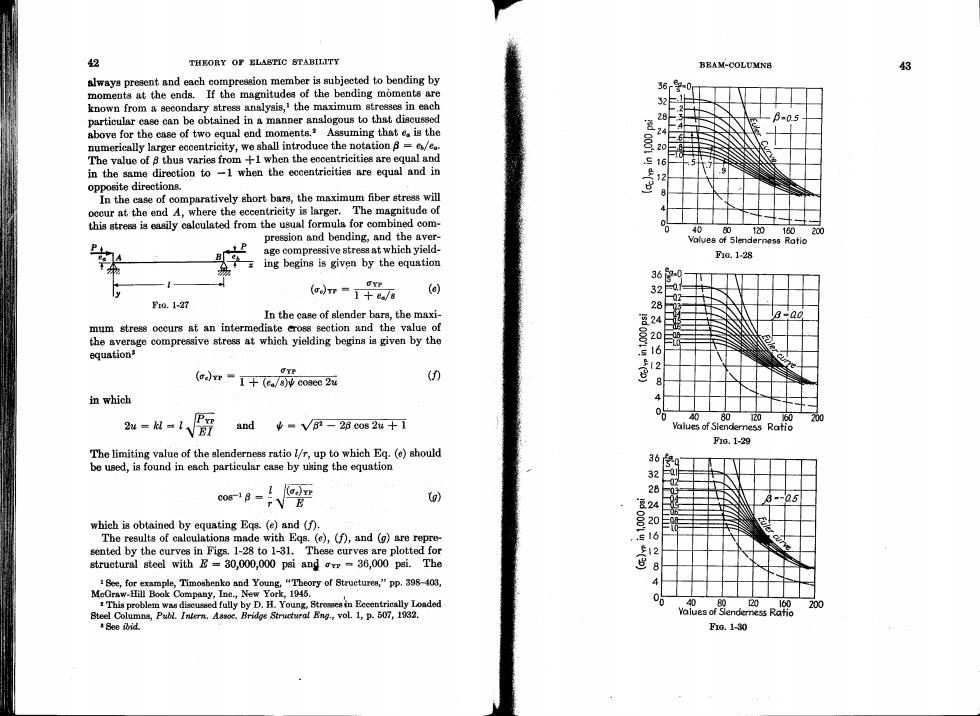
2 THEORY OF ELASTIC STABILITY BEAM-COLUMN8 43 always present and each compression member is subjected to bending by moments at the ends.If the magnitudes of the bending moments are known from a secondary stress analysis,'the maximum stresses in each 52 particular case can be obtained in a manner analogous to that discussed 28 B-0.5 above for the case of two equal end moments.Assuming that e is the 24 numerically larger eccentricity,we shall introduce the notation =/e. 0001 20 The value of 8 thus varies from +1 when the eccentricities are equal and 16 in the same direction to -1 when the eccentricities are equal and in 9 opposite directions. In the case of comparatively short bars,the maximum fiber stress will occur at the end A,where the eccentricity is larger.The magnitude of this stress is easily calculated from the usual formula for combined com- 0 40 pression and bending,and the aver- 80 120160 age compressive stress at which yield- Vaives of Slenderness Ratio 200 Fa.1-28 ing begins is given by the equation 36 OYP (crr=1+a/8 (e) F0.1-27 In the case of slender bars,the maxi- 8-00 mum stress occurs at an intermediate cross section and the value of the average compressive stress at which yielding begins is given by the 1234062 8 equation UTP (1+(e/s)cosec 2u (0 8 in which 4 P型 2w=-1VE7 80 120 650 200 and ¥■V62-26c082w十1 Values of Slenderness Ratio F1G.1-29 The limiting value of the slenderness ratio l/r,up to which Eq.(e)should be used,is found in each particular case by using the equation 36 2 r E Vg) which is obtained by equating Egs.(e)and (f). 2 The results of calculations made with Eqs.(e),(f),and (g)are repre- sented by the curves in Figs.1-28 to 1-31.These curves are plotted for struetural steel with E=30,000,000 psi andv=36,000 psi.The ( 2 1 See,for example,Timoshenko and Young,"Theory of Structures,"pp.398-403, MeGraw-Hill Book Company,Ine.,New York,1945. This problem was discusaed fully by D.H.Young.Stroein Eecentrically Loaded 00 20 160 200 Steel Columns,Publ.Intern.Aasoc.Bridge Structura!Eng.,vol.1,p.507,1032. Yalues of Slendemess Ratio See ibid. Fa.1-30
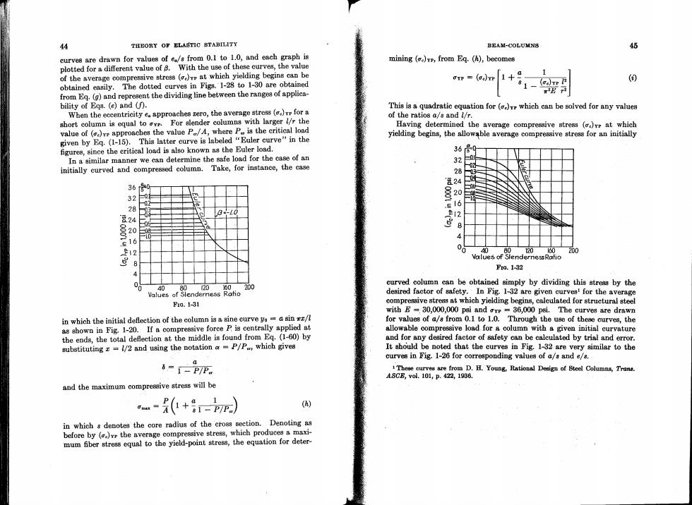
44 THEORY OF ELASTIC STABILITY BEAM-COLUMN8 45 curves are drawn for values of e/s from 0.1 to 1.0,and each graph is mining ()yr,from Eq.(h),becomes plotted for a different value of B.With the use of these curves,the value of the average compressive stress (at which yielding begins can be OTP=(0)+9 (③ obtained easily.The dotted curves in Figs.1-28 to 1-30 are obtained from Eq.(g)and represent the dividing line between the ranges of applica- bility of Eqs.(e)and (f). This is a quadratic equation for (which can be solved for any values When the eccentricity e approaches zero,the average stress (for a of the ratios a/s and l/r. short column is equal to r.For slender columns with larger l/r the Having determined the average compressive stress ()vr at which value of ()rr approaches the value P/A,where P is the critical load given by Eq.(1-15).This latter curve is labeled "Euler curve"in the yielding begins,the allowable average compressive stress for an initially figures,since the critical load is also known as the Euler load. 36 In a similar manner we can determine the safe load for the case of an 32 initially curved and compressed column.Take,for instance,the case &24 36 32 0 o 28 3-.0 24 2 20 0 0 16 12 06 80 ,1 0 200 Values of StendernessRatio 8 F0.1-32 4 00 40 20 为0 200 curved column can be obtained simply by dividing this stress by the Values of Slenderress Ratio desired factor of safety.In Fig.1-32 are given curves!for the average Fig.1-31 compressive stress at which yielding begins,calculated for struetural steel with B=30,000,000 psi and ore =36,000 psi.The curves are drawn in which the initial deflection of the column is a sine curve yo=a sin xx/l for values of a/s from 0.1 to 1.0.Through the use of these curves,the as shown in Fig.1-20.If a compressive force P is centrally applied at allowable compressive load for a column with a given initial curvature the ends,the total deflection at the middle is found from Eq.(1-60)by and for any desired factor of safety can be calculated by trial and error. substituting r =1/2 and using the notation a P/P,which gives It ahould be noted that the curves in Fig.1-32 are very similar to the curves in Fig.1-26 for corresponding values of a/s and e/8. 6=1-PP 1These curves are from D.H.Young,Rational Deaign of Steel Columna,Trans. ASCB,vol.101,P.422,1836 and the maximum compressive stress will be -+-r) () in which s denotes the core radius of the cross section.Denoting as before by ()vr the average compressive stress,which produces a maxi- mum fber stress equal to the yield-point stress,the equation for deter
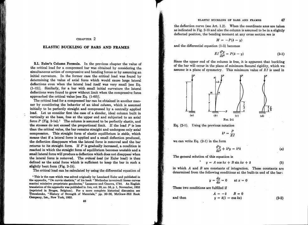
ELASTIC BUCKLING OF BARS AND FRAMES 47 the deflection curve (see Art.1.2).When the coordinate axes are taken as indicated in Fig.2-16 and also the column is assumed to be in a slightly deflected position,the bending moment at any eross section mn is CHAPTER 2 M=-P(8-) ELASTIC BUCKLING OF BARS AND FRAMES and the differential equation (1-3)becomes B12=P6-) (2-1) 2.1.Euler's Column Formula.In the previous chapter the value of Sinee the upper end of the column is free,it is apparent that buckling the critical load for a compressed bar was obtained by considering the of the bar will occur in the plane of minimum flexural rigidity,which we simultaneous action of compressive and bending forces or by assuming an assume is a plane of symmetry.This minimum value of E/is used in initial curvature.In the former case the eritical load was found by determining the value of axial force which would cause large lateral deflections even when the lateral load itself was very small [see Eq. (1-15)1.Similarly,for a bar with small initial curvature the lateral deflections were found to grow without limit when the compressive force approached the critical value [see Eg.(1-60)]. The critical load for a compressed bar can be obtained in another man- ner by considering the behavior of an ideal column,which is assumed initially to be perfectly straight and compressed by a centrally applied load.Let us consider first the case of a slender,ideal column built in 家 破 vertically at the base,free at the upper end and subjected to an axial (bl (c】 d force P (Fig.2-1a).1 The column is assumed to be perfectly elastic,and FG.2-1 the stresses do not exceed the proportional limit.If the load P is less Eq.(2-1).Using the previous notation than the critical value,the bar remains straight and undergoes only axial compression.This straight form of elastic equilibrium is stable,which k=EI means that if a lateral force is applied and a small deflection produced, the deflection disappears when the lateral force is removed and the bar we can write Eg.(2-1)in the form returns to its straight form.If P is gradually increased,a condition is reached in which the straight form of equilibrium becomes unstable and a 器+- (a) small lateral force will produce a deflection which does not disappear when the lateral force is removed.The critical load (or Euler load)is then The general solution of this equation is defined as the axial force which is sufficient to keep the bar in such a y=A co8kz +B gin ka+8 ) slightly bent form (Fig.2-16). The critical load can be calculated by using the differential equation of in which A and B are constants of integration.These constants are determined from the following conditions at the built-in end of the bar: This is the case which was solved originally by Leonhard Euler and published in the appendix,"De curvis elasticis,"of his book"Methodus inveniendi lineas curvas maximi minimive proprictate gaudentes,"Lausanne and Geneva,1744.An English y-ds -0at¥=0 translation of the appendix was publiahed in Isis,vol.20,no.58,p.1,November,1033 These two conditions are fulfilled if (reprinted in Bruges,Belgium).For n more complete historical discussion aee Timoehenko,"History of Strength of Materinls,"pp.30-36,MeGraw-Hill Book A=-8B■0 Company,Ine.,New York,1953. and then y=(1-co8k红) (22) 46