integral over the circuit,it is clear that B(r,t)is everywhere proportional to I(t).That is,if we double the current,B at any point in space will also double.It then follows that the magnetic flux itself must be proportional to /because it is the surface integral of B, and B is everywhere proportional to I.That is, (11.4.4) Therefore we can define the self-inductance L by Φ()=LI() (11.4.5) where G-) (11.4.6) So the magnetic flux is a constant L times the current.Note that L is a constant in the sense that it stays the same as long as we do not change the geometry of the circuit.If we change the geometry of the circuit(for example we halve the radius of the circle in our Figure 11.4.1),we will change L,but for a given geometry,L does not change.Even though it may be terrifically difficult to do the integrals in Eq.(11.4.6),once we have done it for a given circuit geometry we know L,and L is a constant for that geometry. The quantity L is called the self-inductance of the circuit,or simply the inductance. From the definition in (11.4.6),you can show that the dimensions of L are uo times a length. Regardless of how hard or easy it is to compute L,it is a constant for a given circuit geometry and now we can write down the equation that governs the time evolution of I. If (t)=LI(t),then d (t)/dt=Ldl(t)/dt,and Eq.(11.4.1)becomes -e+/R=-LdI (11.4.7) dt If we divide Eq.(11.4.7)by L and rearrange terms,we find that the equation that determines the time dependence of is 11-16
11-16 integral over the circuit, it is clear that ! B( ! r,t) is everywhere proportional to I(t). That is, if we double the current, ! B at any point in space will also double. It then follows that the magnetic flux itself must be proportional to I , because it is the surface integral of ! B , and ! B is everywhere proportional to I . That is, !B (t) = ! B( ! r,t)" nˆda S (t) # = µ0 I(t) 4$ d ! s% & ! r ' % ! ( r ) ! r ' % ! ( r ) "# 3 ( ) * + * , - * . * " nˆ da S # = I(t) µ0 4$ d ! s% & ! r ' % ! ( r ) ! r ' % ! ( r ) "# 3 ( ) * + * , - * . * " nˆ da S # . (11.4.4) Therefore we can define the self-inductance L by !B (t) = LI(t) (11.4.5) where L = µ0 4! d ! s" # ! r $ " ! ( r ) ! r $ " ! ( r ) "% 3 & ' ( ) ( * + ( , ( - nˆ da S % . (11.4.6) So the magnetic flux is a constant L times the current. Note that L is a constant in the sense that it stays the same as long as we do not change the geometry of the circuit. If we change the geometry of the circuit (for example we halve the radius of the circle in our Figure 11.4.1), we will change L , but for a given geometry, L does not change. Even though it may be terrifically difficult to do the integrals in Eq. (11.4.6), once we have done it for a given circuit geometry we know L , and L is a constant for that geometry. The quantity L is called the self-inductance of the circuit, or simply the inductance. From the definition in (11.4.6), you can show that the dimensions of L are µ0 times a length. Regardless of how hard or easy it is to compute L , it is a constant for a given circuit geometry and now we can write down the equation that governs the time evolution of I . If !B (t) = LI(t) , then d!B (t) / dt = LdI(t) / dt , and Eq. (11.4.1) becomes !" + IR = !L dI dt . (11.4.7) If we divide Eq. (11.4.7) by L and rearrange terms, we find that the equation that determines the time dependence of I is
(11.4.8) dt'L'L We shall explore the solution to this equation in Example 11.6.1. 11.4.2 Kirchhoff's Loop Rule Modified for Inductors:a Warning We can write the governing equation for I(t)from above as ∑Ay=E-IR-L业=0 (11.4.9) dt where we have now cast it in a form that "looks like"a version of Kirchhoff's Second Law,a rule that is often quoted in elementary electromagnetism texts.Kirchhoff's Second Law states that the sum of the potential drops around a circuit is zero.In a circuit with no inductance,this is just a statement that the line integral of the electric field around the circuit is zero,which is certainly true if there is no time variation.However, in circuits with currents that vary in time,this "Law"is no longer true. Unfortunately,many elementary texts choose to approach circuits with inductance by preserving "Kirchhoffs Second Law",or the loop theorem,by specifying that if the inductor is traversed in the direction of the current,the "potential drop"across an inductor is -Ldl(t)/dt.Use of this formalism will give the correct equations.However,the continued use of Kirchhoff's Second Law with inductors is misleading at best,for the following reasons. The continued use of Kirchhoff's Second Law in this way gives the right equations,but it confuses the physics.In particular,saying that there is a "potential drop"across the inductor of-Ldl(t)/dt implies that there is an electric field in the inductor such that the integral of E through the inductor is equal to -Ldl(t)/dt.This is not always,or even usually,true.For example,suppose in our "one-loop"inductor (Figure 11.4.1)that the wire making up the loop has negligible resistance compared to the resistance R.The integral of E through our "one-loop"inductor above is then very small,NOT -Ldl(t)/dt.Why is it very small?Well,to repeat our assertion above For a single loop circuit,the current is to an good approximation the same in all parts of the circuit This is just as valid in a circuit with inductance.Again,although the current may start out at t=0 unequal in different parts of the circuit,those inequalities imply that charge is piling up somewhere.The accumulating charge at the pile-up will quickly produce an electric field,and this electric field is always in the sense so as to smooth out the inequalities in the current.In this particular case,if the conductivity of the wires 11-17
11-17 dI dt + R L I = ! L . (11.4.8) We shall explore the solution to this equation in Example 11.6.1. 11.4.2 Kirchhoff's Loop Rule Modified for Inductors: a Warning We can write the governing equation for I(t) from above as !Vi i " = # $ IR $ L dI dt = 0 (11.4.9) where we have now cast it in a form that "looks like" a version of Kirchhoff's Second Law, a rule that is often quoted in elementary electromagnetism texts. Kirchhoff's Second Law states that the sum of the potential drops around a circuit is zero. In a circuit with no inductance, this is just a statement that the line integral of the electric field around the circuit is zero, which is certainly true if there is no time variation. However, in circuits with currents that vary in time, this "Law" is no longer true. Unfortunately, many elementary texts choose to approach circuits with inductance by preserving "Kirchhoff's Second Law", or the loop theorem, by specifying that if the inductor is traversed in the direction of the current, the "potential drop" across an inductor is !LdI(t) / dt . Use of this formalism will give the correct equations. However, the continued use of Kirchhoff's Second Law with inductors is misleading at best, for the following reasons. The continued use of Kirchhoff's Second Law in this way gives the right equations, but it confuses the physics. In particular, saying that there is a "potential drop" across the inductor of !LdI(t) / dt implies that there is an electric field in the inductor such that the integral of ! E through the inductor is equal to !LdI(t) / dt . This is not always, or even usually, true. For example, suppose in our "one-loop" inductor (Figure 11.4.1) that the wire making up the loop has negligible resistance compared to the resistance R . The integral of ! E through our "one-loop" inductor above is then very small, NOT !LdI(t) / dt . Why is it very small? Well, to repeat our assertion above For a single loop circuit, the current I is to an good approximation the same in all parts of the circuit This is just as valid in a circuit with inductance. Again, although the current may start out at t = 0 unequal in different parts of the circuit, those inequalities imply that charge is piling up somewhere. The accumulating charge at the pile-up will quickly produce an electric field, and this electric field is always in the sense so as to smooth out the inequalities in the current. In this particular case, if the conductivity of the wires
making up our one-loop inductor is very large,then there will be a very small electric field in those wires,because it takes only a small electric field to drive any current you need.The amount of current needed is determined in part by the larger resistance in other parts of the circuit,and it is the charge accumulation at the ends of those low conductivity resistors that cancel out the field in the inductor and enhance it in the resistor,maintaining a constant current in the circuit. One final point may confuse the issue even further.If you have ever put the probes of a voltmeter across the terminals of an inductor (with very small resistance)in a circuit, what you measured on the meter of the voltmeter was a "voltage drop"of-Ldl(t)/dt. But that is not because there is an electric field in the inductor!It is because putting the voltmeter in the circuit will result in a time changing magnetic flux through the voltmeter circuit,consisting of the inductor,the voltmeter leads,and the large internal resistor in the voltmeter.A current will flow in the voltmeter circuit because there will be an electric field in the large internal resistance of the voltmeter,with a potential drop across that resistor of-Ldl(t)/dt,by Faraday's Law applied to the voltmeter circuit,and that is what the voltmeter will read.The voltmeter as usual gives you a measure of the potential drop across its own internal resistance,but this is not a measure of the potential drop across the inductor.It is a measure of the time rate of change of magnetic flux in the voltmeter circuit!As before,there is only a very small electric field in the inductor if it has a very small resistance compared to other resistances in the circuit. 11.4.3 Example Voltmeter Readings with Time Changing Magnetic Fields We can think of a voltmeter as a device that registers the line integralE.ds along a path from the clip of its (+)lead to the clip of its (-)lead.Part of the path lies inside the voltmeter itself.The path may also be part of a loop,which is completed by some external path from the(-)clip to the(+)clip.With that in mind,consider the arrangement in the Figure 11.4.2 Meter 1 dB 500 >0 dt B- 309 Meter 2 Figure 11.4.2 Two voltmeters and a time changing magnetic field inside a solenoid 11-18
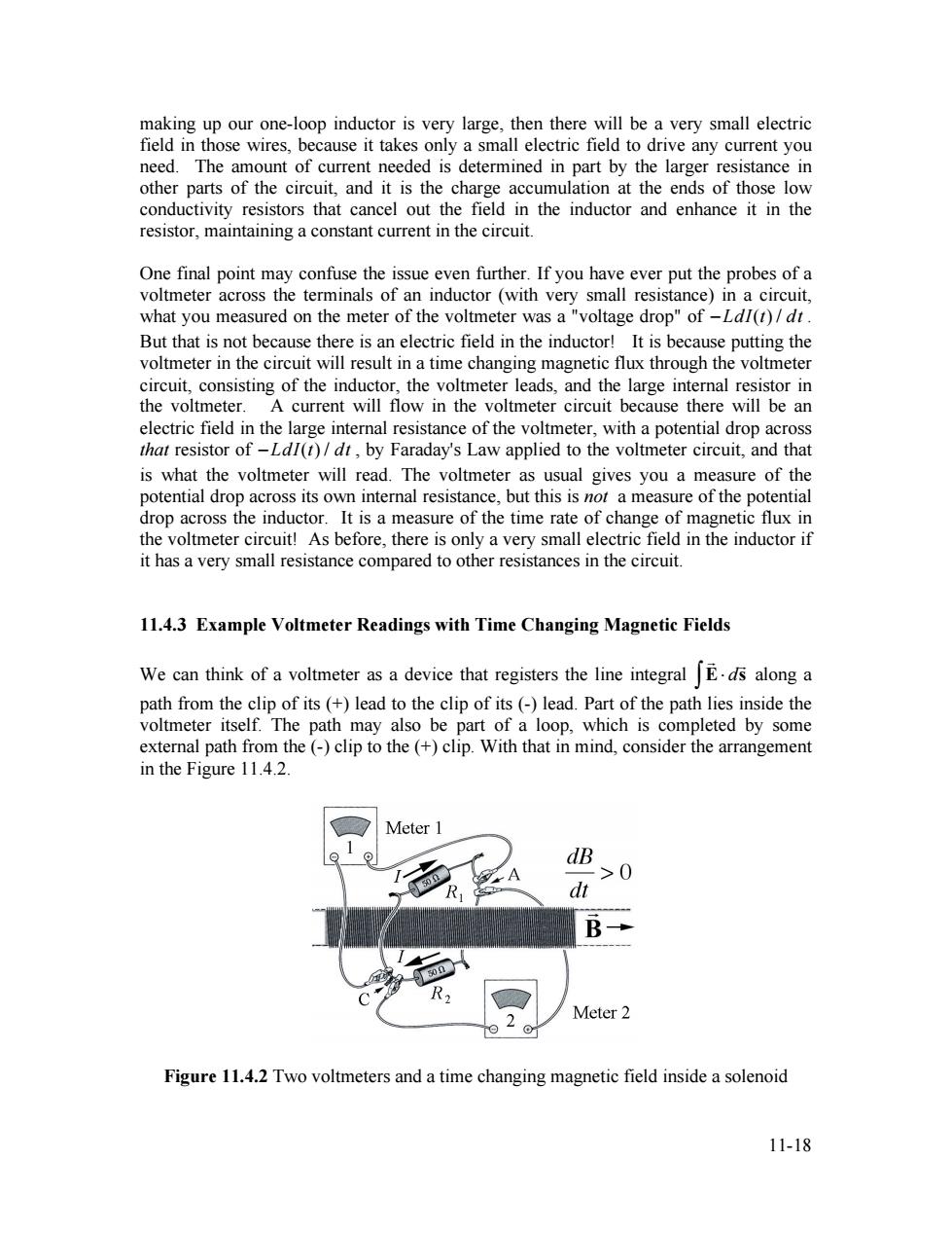
11-18 making up our one-loop inductor is very large, then there will be a very small electric field in those wires, because it takes only a small electric field to drive any current you need. The amount of current needed is determined in part by the larger resistance in other parts of the circuit, and it is the charge accumulation at the ends of those low conductivity resistors that cancel out the field in the inductor and enhance it in the resistor, maintaining a constant current in the circuit. One final point may confuse the issue even further. If you have ever put the probes of a voltmeter across the terminals of an inductor (with very small resistance) in a circuit, what you measured on the meter of the voltmeter was a "voltage drop" of !LdI(t) / dt . But that is not because there is an electric field in the inductor! It is because putting the voltmeter in the circuit will result in a time changing magnetic flux through the voltmeter circuit, consisting of the inductor, the voltmeter leads, and the large internal resistor in the voltmeter. A current will flow in the voltmeter circuit because there will be an electric field in the large internal resistance of the voltmeter, with a potential drop across that resistor of !LdI(t) / dt , by Faraday's Law applied to the voltmeter circuit, and that is what the voltmeter will read. The voltmeter as usual gives you a measure of the potential drop across its own internal resistance, but this is not a measure of the potential drop across the inductor. It is a measure of the time rate of change of magnetic flux in the voltmeter circuit! As before, there is only a very small electric field in the inductor if it has a very small resistance compared to other resistances in the circuit. 11.4.3 Example Voltmeter Readings with Time Changing Magnetic Fields We can think of a voltmeter as a device that registers the line integral ! E! d ! s " along a path from the clip of its (+) lead to the clip of its (-) lead. Part of the path lies inside the voltmeter itself. The path may also be part of a loop, which is completed by some external path from the (-) clip to the (+) clip. With that in mind, consider the arrangement in the Figure 11.4.2. Figure 11.4.2 Two voltmeters and a time changing magnetic field inside a solenoid
The solenoid is so long that its external magnetic field is negligible.Its cross section is 20 cm2in area,and the field inside is to the right and increasing at the rate of 102T.s Two identical voltmeters are connected as shown to points A and C on the loop,which encloses the solenoid and contains the two 50-ohm resistors.The voltmeters are capable of reading microvolts and have high internal resistance.What will each voltmeter read? Make sure you answer is consistent,from every point of view,with Faraday's Law(Eq. 10.3.2) Solution:Consider the loop containing resistors 1 and 2 with the solenoid passing through it.Choose A in the direction opposite the magnetic field,then the magnetic flux is B.A=-B4.The change in the magnetic flux and hence the emf through the loop is given by £=- dB二+ B A=(10-2T·s)(20×104m2)=2×10⁻⁵Tm2.s=20V dt dt Therefore the current in the loop is 1=lL-20 2R1002 =0.2lA Because the emf is positive,the current is clockwise when looking from right to left in Figure 11.4.2. Now let's consider the loop that includes resistor 1 and voltmeter 1 that does not enclose magnetic flux.Voltmeter 1 measures the line integral inside the voltmeter from the positive terminal to the negative terminal,hence the meter measures E inside I If we complete the path from the negative terminal through resistor 1 to the positive terminal then, 「E·ds=R=(2A502)=10V Because there is no changing magnetic flux through this loop,Faraday's Law is Eds+Eds=0. inside l outside1 Therefore 11-19
11-19 The solenoid is so long that its external magnetic field is negligible. Its cross section is 20 cm2 in area, and the field inside is to the right and increasing at the rate of 10!2 T "s -1 . Two identical voltmeters are connected as shown to points A and C on the loop, which encloses the solenoid and contains the two 50-ohm resistors. The voltmeters are capable of reading microvolts and have high internal resistance. What will each voltmeter read? Make sure you answer is consistent, from every point of view, with Faraday’s Law (Eq. 10.3.2). Solution: Consider the loop containing resistors 1 and 2 with the solenoid passing through it. Choose ! A in the direction opposite the magnetic field, then the magnetic flux is ! B! ! A = "BA. The change in the magnetic flux and hence the emf through the loop is given by ! = " d#B dt = + dB dt A = (10"2 T $s -1 )(20 % 10"4 m2 ) = 2 % 10"5 T $m2 $s -1 = 20 µV . Therefore the current in the loop is I = ! 2R = 20 µV 100 " = 0.2 µA . Because the emf is positive, the current is clockwise when looking from right to left in Figure 11.4.2. Now let’s consider the loop that includes resistor 1 and voltmeter 1 that does not enclose magnetic flux. Voltmeter 1 measures the line integral inside the voltmeter from the positive terminal to the negative terminal, hence the meter measures !V1 = ! E" d ! s + inside 1 # $ . If we complete the path from the negative terminal through resistor 1 to the positive terminal then, ! E! d ! s " outside 1 + # = IR1 = (.2 µA)(50 $) = 10 µV . Because there is no changing magnetic flux through this loop, Faraday’s Law is ! E! d ! s + inside 1 " # + ! E! d ! s " outside 1 + # = 0. Therefore