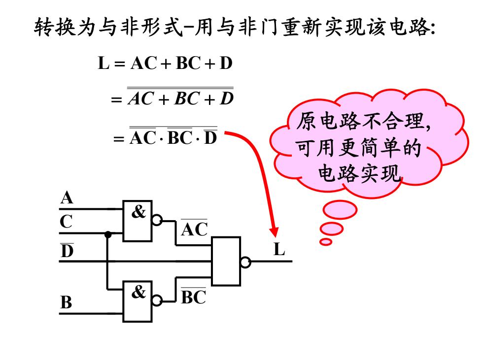
转换为与非形式-用与非门重新实现该电路: L=AC+BC+D =AC+BC+D 原电路不合理, =AC.BC.D 可用更简单的 电路实现 A C B
& A C AC 转换为与非形式-用与非门重新实现该电路: DBCACL AC C DB DBCAC D & B BC 原电路不合理, 可用更简单的 电路实现 L
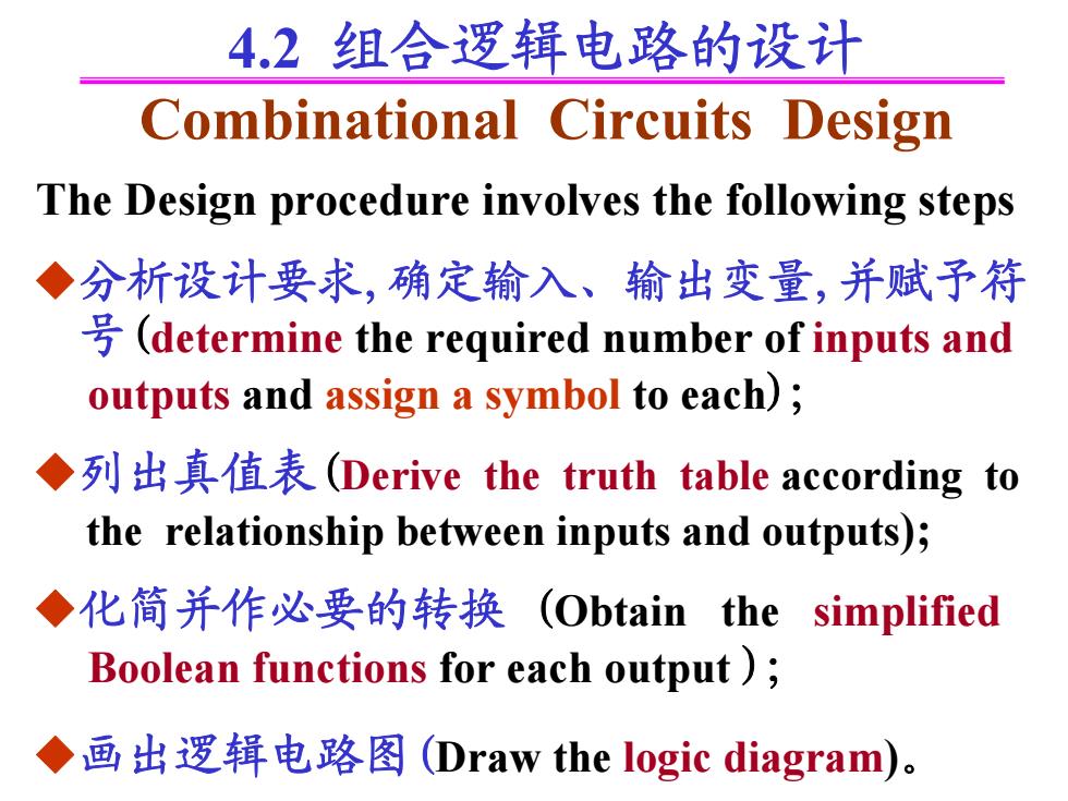
4.2组合逻辑电路的设计 Combinational Circuits Design The Design procedure involves the following steps ◆分析设计要求,确定输入、输出变量,并赋予符 (determine the required number of inputs and outputs and assign a symbol to each); ◆列出真值表(Derive the truth table according to the relationship between inputs and outputs); ◆化简并作必要的转换(Obtain the simplified Boolean functions for each output ) ◆画出逻辑电路图(Draw the logic diagram)
◆分析设计要求,确定输入、输出变量,并赋予符 号(determine the required number of inputs and outputs and assign a symbol to each); ◆列出真值表(Derive the truth table according to the relationship between inputs and outputs); ◆化简并作必要的转换 (Obtain the simplified Boolean functions for each output ); ◆画出逻辑电路图(Draw the logic diagram)。 The Design procedure involves the following steps 4.2 组合逻辑电路的设计 Combinational Circuits Design

例4设计1个用与非门实现的交通信号灯检测 报警电路:若交通信号灯控制电路失灵,就可能 会出现信号灯无效组合(两灯或三灯同时发光), 检测报警电路能在信号灯出现无效组合时,发出 报警信号。 ◆INPUT:红A、黄B、灯C B 0 0 OUTPUT:报警信号L。 0 0 ◆列出真值表 0 设:灯亮为“1”,灯灭为“0”; 0 报警为“1”,不报为“0
例4 设计1个用与非门实现的交通信号灯检测 报警电路: 若交通信号灯控制电路失灵, 就可能 会出现信号灯无效组合(两灯或三灯同时发光), 检测报警电路能在信号灯出现无效组合时,发出 报警信号。 A B C L 0 0 0 0 0 1 0 1 0 0 1 1 1 0 0 1 0 1 1 1 0 1 1 1 ◆INPUT: 红A 、黄B 、灯C OUTPUT: 报警信号 L。 设: 灯亮为“1”, 灯灭为“0”; 报警为“1”, 不报为“0”。 ◆列出真值表 0 0 0 0 1 1 1 1

◆写出逻辑表达式 0 L=AB+BC+CA =AB+BC+AC =AB+BC+AC ◆画逻辑图 EWB演示例3 B C & 0 0 0 o 变换为与非形式 0 0 0 0 0 0 0 0 0
L B C A 1 1 1 1 0 0 0 0 CABCABL ACBCAB ACBCAB ◆画逻辑图 & & & & A B C ◆写出逻辑表达式 A B C L 0 0 0 0 0 1 0 1 0 0 1 1 1 0 0 1 0 1 1 1 0 1 1 1 0 0 0 0 1 1 1 1 变换为与非形式 EWB演示例 3

例5由3台电动机驱动的物料传输系统,为避免物料积压, 要求:A开机,B必须开机;B开机,C也必须开机,否则发出 控制信号,关闭装料阈门.试用与非门实现该控制功能。 ◆列出真值表 B 回A 0 0 0 0 0 1 0 0 ◆INPUT:A、B、C的状态。 0 0 开机“1”,停机“0” 0 OUTPUT:控制信号L。有“1,没有“0
例5 由3台电动机驱动的物料传输系统,为避免物料积压, 要求: A开机, B必须开机; B开机, C也必须开机, 否则发出 控制信号, 关闭装料阈门. 试用与非门实现该控制功能。 A B C ◆INPUT: A、B、C的状态。 开机 “1”,停机 “0” OUTPUT: 控制信号L。有 “1”,没有 “0” A B C L 0 0 0 0 0 1 0 1 0 0 1 1 1 0 0 1 0 1 1 1 0 1 1 1 ◆列出真值表 0 0 0 0 1 1 1 1