Chapter 4 Motion Dimensional Measurement by Yixin Ma 20/03/2013 2/51 Contents: 1.Introduction 2.Fundamental Standards 3.Relative Displacement:Translational and Rotational 4.Relative Velocity:Translational and Rotational 5.Relative Acceleration Measurement 6.Seismic-(Absolute-)Acceleration Pickups (Accelerometers) 7.Calibration of Vibration Pickups 8.Jerk Pickups 9.Pendulous(Gravity-Referenced)Angular-Displacement Sensors 10.Gyroscopic (Absolute)Angular-Displacement and Velocity Sensors 11.Coordinate-Measuring Machines 12.Surface-Finish Measurement 13.Machine Vision 14.The Global-Positioning System(GPS)
Chapter 4 Motion & Dimensional Measurement by Yixin Ma 20/03/2013 Contents: 1. Introduction 2. Fundamental Standards 3. Relative Displacement: Translational and Rotational 4. Relative Velocity: Translational and Rotational 5. Relative Acceleration Measurement 6. Seismic-(Absolute-) Acceleration Pickups (Accelerometers) 7. Calibration of Vibration Pickups 8. Jerk Pickups 9. Pendulous (Gravity-Referenced) Angular-Displacement Sensors 10. Gyroscopic (Absolute) Angular-Displacement and Velocity Sensors 11. Coordinate-Measuring Machines 12. Surface-Finish Measurement 13. Machine Vision 14. The Global-Positioning System (GPS) 2/51
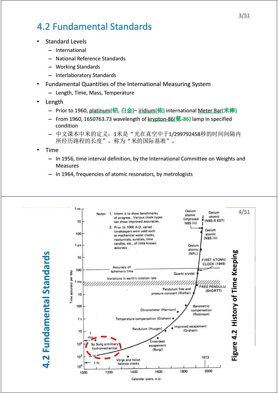
3/51 4.2 Fundamental Standards ·Standard Levels International National Reference Standards 一 Working Standards Interlaboratory Standards Fundamental Quantities of the International Measuring System Length,Time,Mass,Temperature ·Length -Prior to 1960,platinum(铂,白金)-iridium(铱)international Meter Bar(米棒) From 1960,1650763.73 wavelength of krypton-86(-86)lamp in specified condition 中文课本中米的定义:1米是“光在真空中于1/299792458秒的时间间隔内 所经历路程的长度”,称为“米的国际基准”。 。Time In 1956,time interval definition,by the International Committee on Weights and Measures In 1964,frequencies of atomic resonators,by metrologists Cesium Notes:1.Intent is to show benchmarks Cesium 4/51 of progress.Various clock types atomic atomic (improved 10 can show improved accuracies. NBS HI) (NBS-5 EST) 2.Prior to 1000 A.D.varied timekeepers were used such Cesium 100 as mechanical water clocks atomic nocturnials,sundials,time (NBS I) 1 us candles,etc..of little known Cesium accuracy. 10 FIRST ATOMIC CL0CK(1949) Accuracy of 100 ephemeris time Quartz crystal 型 Variations in earth's rotation rate 44444464644446/4464444444444444 Pendulum free and FREE PENDULU (SHORTT) 10 pressure constant (Riefler) 台 100 Barometric Chronometer (Harrison) compensation Robinson】 1 Temperature compensation(Graham). ●improved escapement 10- Pendulum(Huygen) (Graham) 子 Cross-beat 102 escapement hydromechanical (Burgi) 103 1973 Verge and foliot 10 1 hr balance clocks 1000 1200 1400 1600 1800 2000 Calendar years,A.D
4.2 Fundamental Standards • Standard Levels – International – National Reference Standards – Working Standards – Interlaboratory Standards • Fundamental Quantities of the International Measuring System – Length, Time, Mass, Temperature • Length – Prior to 1960, platinum(铂, 白金)– iridium(铱) international Meter Bar(米棒) – From 1960, 1650763.73 wavelength of krypton-86(氪-86) lamp in specified condition – 中文课本中米的定义:1米是“光在真空中于1/299792458秒的时间间隔内 所经历路程的长度”,称为“米的国际基准”。 • Time – In 1956, time interval definition, by the International Committee on Weights and Measures – In 1964, frequencies of atomic resonators, by metrologists 3/51 苏颂及其水运仪象台 4.2 Fundamental Standards Figure 4.2 History of Time Keeping 4/51
5/51 4.3 Relative Displacement:Translational and Rotational I. Calibration ll.Resistive Potentiometers Ill.Resistance Strain Gage IV.Differential Transformers V.Synchros and Resolvers VI.Variable-Inductance Variable-Reluctance Pickups VIl.Eddy-Current Noncontacting Transducers VIll.Capacitance Pickups IX.Piezoelectric Transducers X.Electro-Optical Devices XI.Photographic and Electronic-Imaging Techniques XIl.Photoelastic,Brittle-Coating,and Moir Fringe Stress-Analysis Techniques XIll.Displacement-to-Pressure(Nozzle-Flapper)Transducer XIV.Digital Displacement Transducers(Translational and Rotary Encoders) XV.Ultrasonic Transducers 6/51 4.3 Relative Displacement:Translational and Rotational I.Calibration-Translational Displacement Translation:a uniform movement without rotation ◆Static calibration of translational平移/平动)devices using micrometers(千分尺)usually has accuracy of0.01mm ◆Using level(杠杆)devices or wedge-type(楔形)mechanisms for motion reduction to achieve smaller resolution ◆Using linear encoder(编码器)scales or laser interferometers(千涉仪)to realize greater accuracy ◆Gage Blocks(量块:small blocks of hard,dimensionally stable steel or other material made in sets that can be stacked to provide accurate dimension over a wide range and in small steps. When transducers are calibrated to very high accuracy,it is extremely important to control all interfering and/or modifying inputs such as ambient temperature,electrical excitation to the transducer,etc
4.3 Relative Displacement: Translational and Rotational I. Calibration II. Resistive Potentiometers III. Resistance Strain Gage IV. Differential Transformers V. Synchros and Resolvers VI. Variable-Inductance & Variable-Reluctance Pickups VII. Eddy-Current Noncontacting Transducers VIII. Capacitance Pickups IX. Piezoelectric Transducers X. Electro-Optical Devices XI. Photographic and Electronic-Imaging Techniques XII. Photoelastic, Brittle-Coating, and Moir Fringe Stress-Analysis Techniques XIII. Displacement-to-Pressure (Nozzle-Flapper) Transducer XIV. Digital Displacement Transducers (Translational and Rotary Encoders) XV. Ultrasonic Transducers 5/51 4.3 Relative Displacement: Translational and Rotational I. Calibration – Translational Displacement Translation: a uniform movement without rotation Static calibration of translational( 平 移 / 平 动 ) devices using micrometers(千分尺) usually has accuracy of 0.01mm Using level(杠杆) devices or wedge-type(楔形) mechanisms for motion reduction to achieve smaller resolution Using linear encoder(编码器) scales or laser interferometers (干涉仪) to realize greater accuracy Gage Blocks (量块): small blocks of hard, dimensionally stable steel or other material made in sets that can be stacked to provide accurate dimension over a wide range and in small steps. When transducers are calibrated to very high accuracy, it is extremely important to control all interfering and/or modifying inputs such as ambient temperature, electrical excitation to the transducer, etc. 6/51
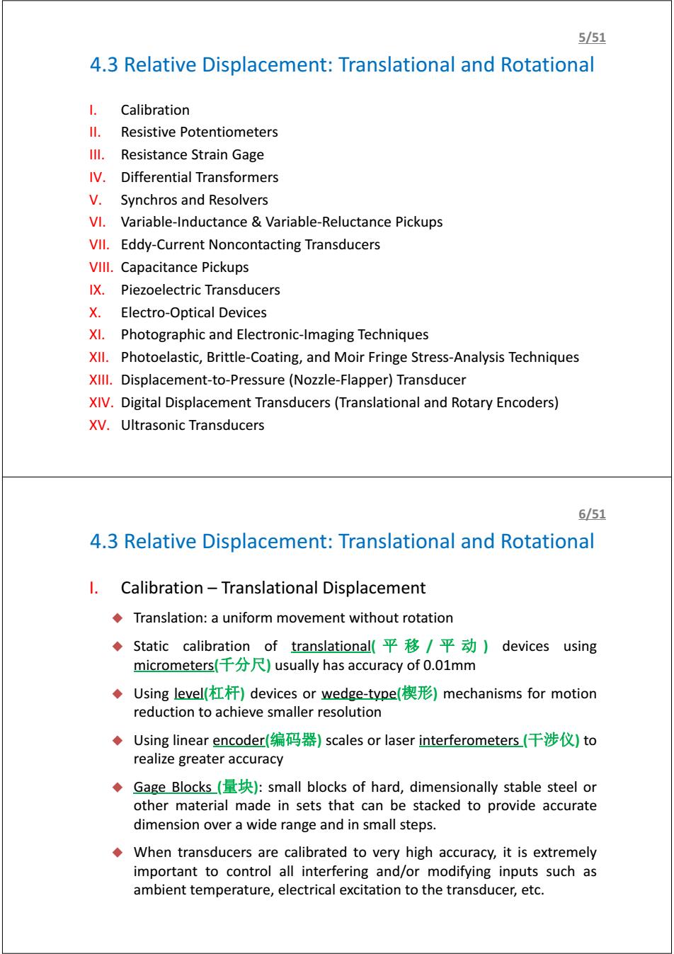
7/51 4.3 Relative Displacement:Translational and Rotational I.Calibration-Rotational Displacement The basic standards for rotational or angular displacement are called angle blocks(角度量块) Angle blocks are carefully made steel blocks about in wide and 3 in long,with a specified angle between the two contact surfaces ◆Angle blocks can be calibrated to0.1 second of arc(弧秒,1弧度=60弧 分,1弧分=60弧秒),but this accuracy is rarely required. A precision dividing head may be used to both produce the angular motion and measure it. Digital absolute shaft angle encoders with electronic angle readouts are available in a wide range and can serve as convenient calibration standards for less accurate devices. 8/51 4.3 Relative Displacement:Translational and Rotational ll.Resistive Potentiometers A resistive potentiometer consists of a resistance element provided with a movable contact. The contact motion can be translation,rotation,or a combination of the two. Loading effects as shown in Figure 4.5a e 1 eex1++01-0 4.1 xi Rm To modify linearity,add a resistor with the same Rm as shown in Figure 4.5b
4.3 Relative Displacement: Translational and Rotational I. Calibration – Rotational Displacement The basic standards for rotational or angular displacement are called angle blocks (角度量块) Angle blocks are carefully made steel blocks about ఱ ఴ in wide and 3 in long, with a specified angle between the two contact surfaces Angle blocks can be calibrated to 0.1 second of arc(弧秒, 1弧度=60弧 分, 1弧分=60弧秒), but this accuracy is rarely required. A precision dividing head may be used to both produce the angular motion and measure it. Digital absolute shaft angle encoders with electronic angle readouts are available in a wide range and can serve as convenient calibration standards for less accurate devices. 7/51 4.3 Relative Displacement: Translational and Rotational II. Resistive Potentiometers A resistive potentiometer consists of a resistance element provided with a movable contact. The contact motion can be translation, rotation, or a combination of the two. Loading effects as shown in Figure 4.5a ୣ ୣ౮ = ଵ ଵା(౮౪ ౮ ା ౦ ౣ )(ଵି౮ ౮౪ ) 4.1 To modify linearity, add a resistor with the same Rm as shown in Figure 4.5b 8/51
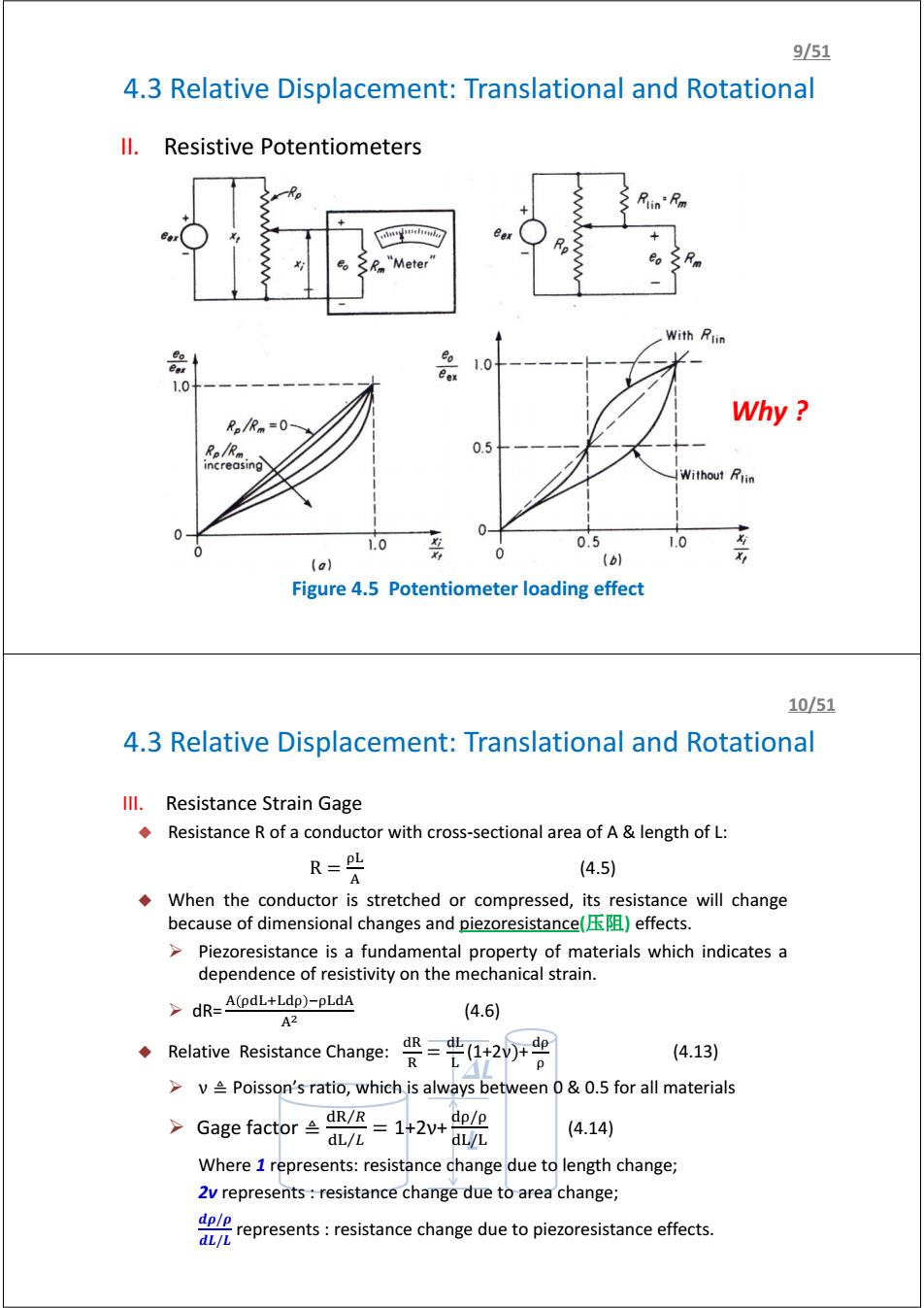
951 4.3 Relative Displacement:Translational and Rotational ll.Resistive Potentiometers Rlin'Fm "Meter With Rtin 品 Bex 1.0 1.0 Why Re/Rm=0- R。R。 0.5 increasing Without Rlin 1.0 0.5 1.0 0 (a) (b) Figure 4.5 Potentiometer loading effect 10/51 4.3 Relative Displacement:Translational and Rotational Ill.Resistance Strain Gage Resistance R of a conductor with cross-sectional area of A length of L: R=PL (4.5) A When the conductor is stretched or compressed,its resistance will change because of dimensional changes and piezoresistance()effects. >Piezoresistance is a fundamental property of materials which indicates a dependence of resistivity on the mechanical strain. >dR=A(pdL+Ldp)-pLdA A2 (4.6) Relative Resistance Change: =20r号 (4.13) p >v Poisson's ratio,which is always between 0&0.5 for all materials >Ga8 efactor2=142+鼢 dL/L (4.14) Where 1 represents:resistance change due to length change; 2v represents resistance change due to area change; represets:resistance change due to piezoresistance effects. dL/L
II. Resistive Potentiometers Figure 4.5 Potentiometer loading effect 4.3 Relative Displacement: Translational and Rotational 9/51 www.vishay.com www.bourns.com Why ? 4.3 Relative Displacement: Translational and Rotational L DL III. Resistance Strain Gage Resistance R of a conductor with cross-sectional area of A & length of L: R = (4.5) When the conductor is stretched or compressed, its resistance will change because of dimensional changes and piezoresistance(压阻) effects. ¾ Piezoresistance is a fundamental property of materials which indicates a dependence of resistivity on the mechanical strain. ¾ dR= ୢାୢ ିୢ మ (4.6) Relative Resistance Change: ୢୖ ୖ = ୢ (1+2ν)+ ୢ (4.13) ¾ ν ≜ Poisson’s ratio, which is always between 0 & 0.5 for all materials ¾ Gage factor ≜ ୢୖ ோ⁄ ୢ ⁄ = 1+2ν+ ୢ/ ୢ/ (4.14) Where 1 represents: resistance change due to length change; 2ν represents : resistance change due to area change; ࣋/࣋ࢊ ࡸࢊ/ࡸ represents : resistance change due to piezoresistance effects. 10/51