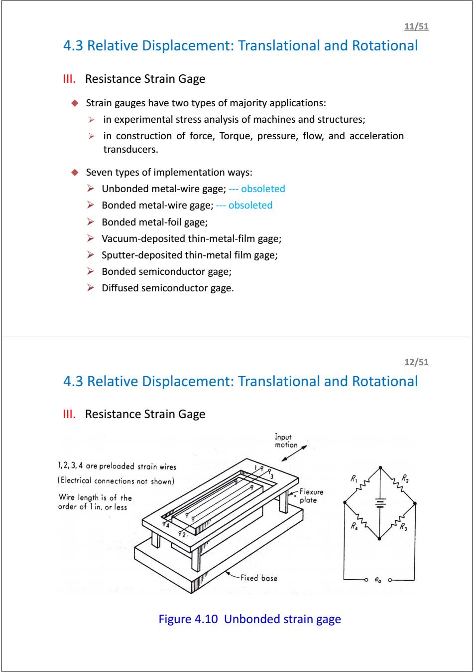
11/51 4.3 Relative Displacement:Translational and Rotational Ill.Resistance Strain Gage Strain gauges have two types of majority applications: in experimental stress analysis of machines and structures; in construction of force,Torque,pressure,flow,and acceleration transducers. Seven types of implementation ways: >Unbonded metal-wire gage;---obsoleted Bonded metal-wire gage;---obsoleted Bonded metal-foil gage; Vacuum-deposited thin-metal-film gage; Sputter-deposited thin-metal film gage; Bonded semiconductor gage; Diffused semiconductor gage. 12/51 4.3 Relative Displacement:Translational and Rotational Ill.Resistance Strain Gage Input motion 1,2,3,4 are preloaded strain wires (Electrical connections not shown) R Wire length is of the Flexure plate order of I in.or less Fixed base Figure 4.10 Unbonded strain gage
4.3 Relative Displacement: Translational and Rotational III. Resistance Strain Gage Strain gauges have two types of majority applications: ¾ in experimental stress analysis of machines and structures; ¾ in construction of force, Torque, pressure, flow, and acceleration transducers. Seven types of implementation ways: ¾ Unbonded metal-wire gage; --- obsoleted ¾ Bonded metal-wire gage; --- obsoleted ¾ Bonded metal-foil gage; ¾ Vacuum-deposited thin-metal-film gage; ¾ Sputter-deposited thin-metal film gage; ¾ Bonded semiconductor gage; ¾ Diffused semiconductor gage. 11/51 4.3 Relative Displacement: Translational and Rotational III. Resistance Strain Gage Figure 4.10 Unbonded strain gage 12/51
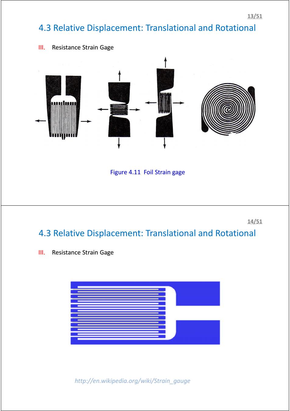
1351 4.3 Relative Displacement:Translational and Rotational Ill.Resistance Strain Gage Figure 4.11 Foil Strain gage 14/51 4.3 Relative Displacement:Translational and Rotational Ill.Resistance Strain Gage http://en.wikipedia.org/wiki/Strain_gauge
4.3 Relative Displacement: Translational and Rotational III. Resistance Strain Gage Figure 4.11 Foil Strain gage 13/51 4.3 Relative Displacement: Translational and Rotational III. Resistance Strain Gage http://en.wikipedia.org/wiki/Strain_gauge 14/51
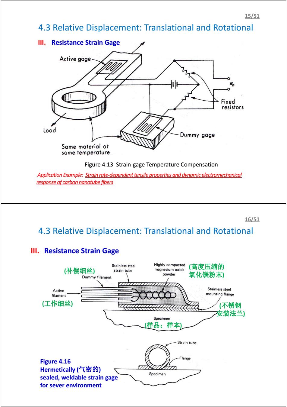
15/51 4.3 Relative Displacement:Translational and Rotational Ill.Resistance Strain Gage Active gage % 0 Fixed resistors Load Dummy gage Some material at same temperature Figure 4.13 Strain-gage Temperature Compensation Application Example:Strain rate-dependent tensile properties and dynamic electromechanical response of carbon nanotube fibers 16/51 4.3 Relative Displacement:Translational and Rotational Ill.Resistance Strain Gage Stainless steel Highly compacted (补偿细丝) (高度压缩的 strain tube magnesium oxide powder Dummy filament 氧化镁粉末) 77 Active Stainless steel filament mounting flange (工作细丝) (不锈钢 安装法兰) Specimen 样品;样本) Strain tube Figure 4.16 Flange Hermetically(气密的) Specimen sealed,weldable strain gage for sever environment
4.3 Relative Displacement: Translational and Rotational III. Resistance Strain Gage Figure 4.13 Strain-gage Temperature Compensation 15/51 Application Example: Strain rate-dependent tensile properties and dynamic electromechanical response of carbon nanotube fibers 4.3 Relative Displacement: Translational and Rotational (样品;样本) (工作细丝) (高度压缩的 氧化镁粉末) (不锈钢 安装法兰) (补偿细丝) III. Resistance Strain Gage Figure 4.16 Hermetically (气密的) sealed, weldable strain gage for sever environment 16/51
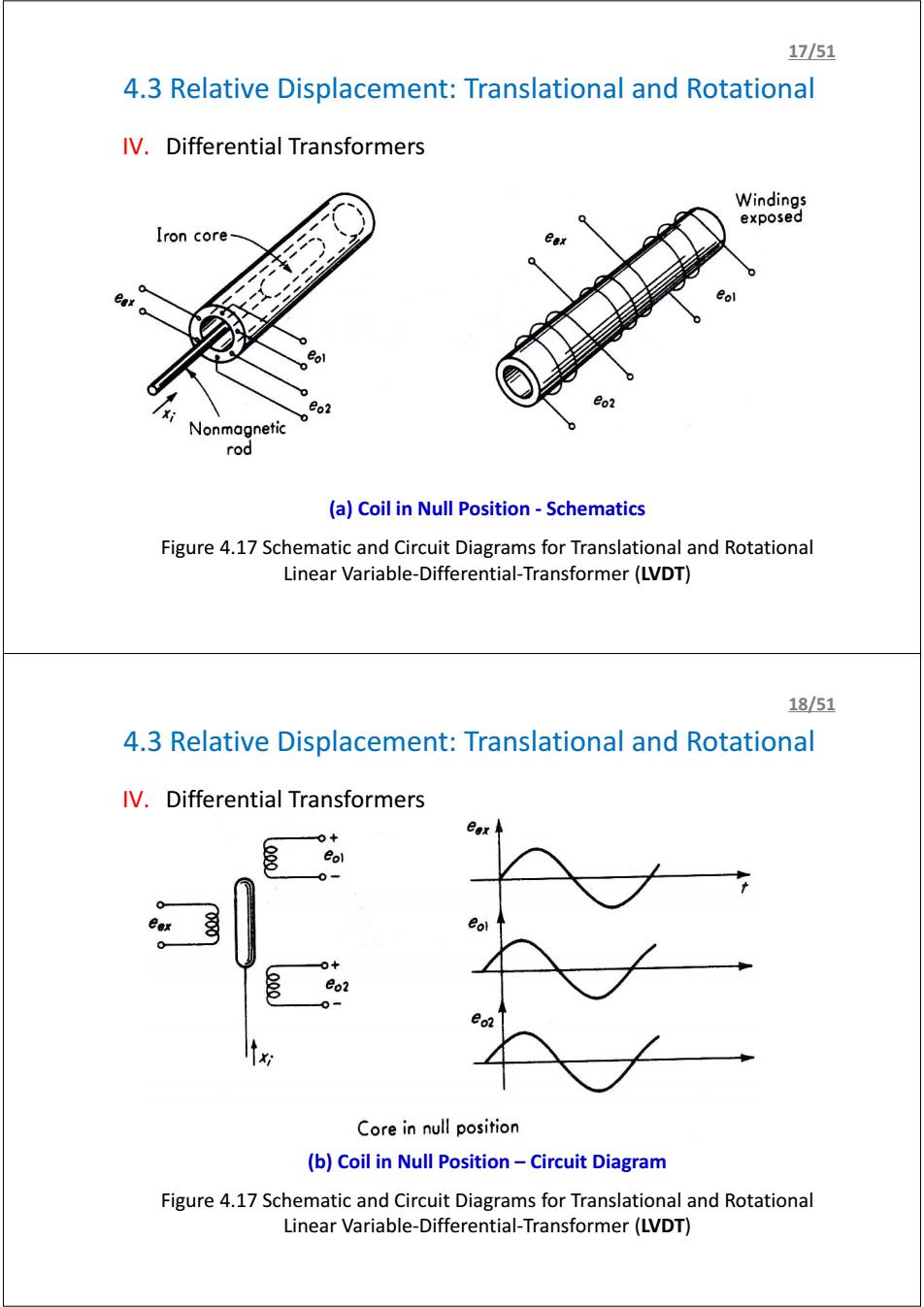
17/51 4.3 Relative Displacement:Translational and Rotational IV.Differential Transformers Windings exposed Iron core eo2 Nonmagnetic rod (a)Coil in Null Position-Schematics Figure 4.17 Schematic and Circuit Diagrams for Translational and Rotational Linear Variable-Differential-Transformer(LVDT) 18/51 4.3 Relative Displacement:Translational and Rotational IV.Differential Transformers eol 0+ eo2 0= Core in null position (b)Coil in Null Position-Circuit Diagram Figure 4.17 Schematic and Circuit Diagrams for Translational and Rotational Linear Variable-Differential-Transformer(LVDT)
4.3 Relative Displacement: Translational and Rotational IV. Differential Transformers (a) Coil in Null Position - Schematics Figure 4.17 Schematic and Circuit Diagrams for Translational and Rotational Linear Variable-Differential-Transformer (LVDT) 17/51 4.3 Relative Displacement: Translational and Rotational IV. Differential Transformers (b) Coil in Null Position – Circuit Diagram Figure 4.17 Schematic and Circuit Diagrams for Translational and Rotational Linear Variable-Differential-Transformer (LVDT) 18/51