Chapter 6 Pressure and Sound Measurement by Yixin Ma 10/04/2013 2/44 Contents 1.Standards and Calibration 2.Basic Methods of Pressure Measurement 3.Deadweight Gages and Manometers 4.Elastic Transducers 5.Vibrating-Cylinder and Other Resonant Transducer 6.High-Pressure Measurement 7.Low-Pressure(Vacuum)Measurement 8.Sound Measurement
Chapter 6 Pressure and Sound Measurement by Yixin Ma 10/04/2013 Contents 1. Standards and Calibration 2. Basic Methods of Pressure Measurement 3. Deadweight Gages and Manometers 4. Elastic Transducers 5. Vibrating-Cylinder and Other Resonant Transducer 6. High-Pressure Measurement 7. Low-Pressure (Vacuum) Measurement 8. Sound Measurement 2/44
3/44 6.1 standards and calibration Definition:P=F/A (N/m2=Pa), Pressure developed at the base of the liquid column is P=pg h Units:1 bar 105 Pa;1 lbf/in2=1 psi 6.895 kPa;1 mmHg 133.32 Pa; 1 atm(Standard atmosphere)=760.00 mmHg (0C)=10332mm Ag(4C) Hg=Mercury;Ag=water ◆Standards: Medium vacuum (about 0.1mmHg)-several 100k Ibflin2:precision mercury columns (manometers)and deadweight piston gages. 0.001mmHg-0.1mmHg:the McLeod vacuum gage. Less than 0 001mmHg:a pressure-dividing technique allows flow through a succession of accurate orifices to relate the low downstream pressure to higher upstream pressure. Measurement Uncertainties: Gage and Pressure Measurement Uncertainties Type of Instrument Range Uncertainty Gas-operated PG 1.4 kPa to 17 MPa ±57ppm Oil-operated PG 700 kPa to 100 MPa ±63ppm 100 MPa to 280 MPa ±60to±150ppm Cil-operated PG 40 to 400 MPa ±186ppm 4/44 6.2 Basic Methods of Pressure Measurement High vacuum region-a variety of special methods not directly related to force measurement are necessary: General pressure measurement-pressure transduced into force: Comparison with known deadweights acting on known areas; Deflection of elastic element subjected to the unknown pressure
6.1 standards and calibration Definition: ܲൌܨ ܣ) ⁄N/m2=Pa), Pressure developed at the base of the liquid column is ࡼ ൌ ࣋ ࢍ ࢎ Units: 1 bar = 105 Pa; 1 lbf/in2 = 1 psi = 6.895 kPa; 1 mmHg = 133.32 Pa; 1 atm (Standard atmosphere) = 760.00 mmHg (0℃) = 10332mm Ag (4℃) Hg=Mercury; Ag=water Standards: Medium vacuum (about 0.1mmHg) - several 100k lbf/in2: precision mercury columns (manometers) and deadweight piston gages. 0.001mmHg - 0.1mmHg: the McLeod vacuum gage. Less than 0.001mmHg: a pressure-dividing technique allows flow through a succession of accurate orifices to relate the low downstream pressure to higher upstream pressure. Measurement Uncertainties: 3/44 6.2 Basic Methods of Pressure Measurement High vacuum region - a variety of special methods not directly related to force measurement are necessary: General pressure measurement - pressure transduced into force: ¾ Comparison with known deadweights acting on known areas; ¾ Deflection of elastic element subjected to the unknown pressure. 4/44

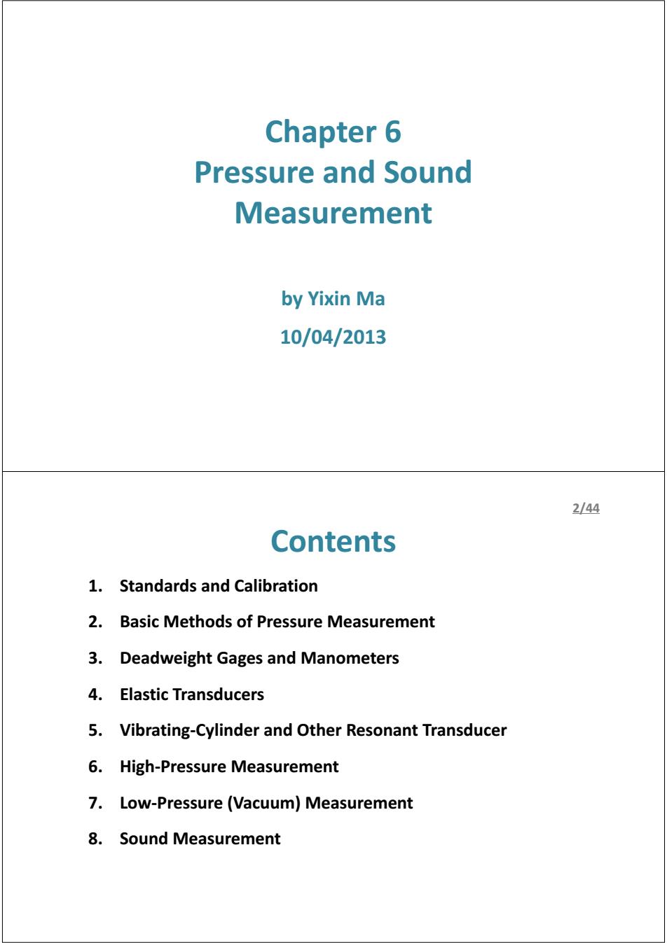
5/44 6.3.1 Deadweight Gages ◆Principles: Air buoyoncy on weights and piston >Mainly employed as standards for the calibration of less accurate gages or transducers. Gage to be >The gage to be calibrated is Oil film colibrated connected to a chamber filled with fluid whose pressure can be Goge reference point adjusted by some type of pump and bleed valye(泄流阀). 5 s >The chamber also connects with a vertical piston-cylinder to which various standard weights may be applied. Bleed When the piston and weights valve are seen to "float",the fluid "gage" pressure equal the deadweight Figure 6.2 Deadweight Gage Calibrator supported by piston,divided by the piston area. 6/44 6.3.1 Deadweight Gages Refinements and Corrections: >Piston and cylinder deform under pressure; >To reduce/correct the friction force between the cylinder and piston. >A small clearance between the piston and the cylinder is necessary to allow fluid to flow from high pressure end to low pressure end.The flow produces a viscous shear force tending to support part of the deadweight. >The effective area generally is taken as the average of the piston and cylinder areas. >Height differences between the lower and of the piston and the reference point for the gage being calibrated. >Temperature effects on areas of piston and cylinder. >Air and pressure-medium buoyancy effects. >Local gravity conditions
6.3.1 Deadweight Gages Principles: ¾ Mainly employed as standards for the calibration of less accurate gages or transducers. ¾ The gage to be calibrated is connected to a chamber filled with fluid whose pressure can be adjusted by some type of pump and bleed valve (泄流阀). ¾ The chamber also connects with a vertical piston-cylinder to which various standard weights may be applied. ¾ When the piston and weights are seen to “float”, the fluid “gage” pressure equal the deadweight supported by piston, divided by the piston area. Figure 6.2 Deadweight Gage Calibrator 5/44 6.3.1 Deadweight Gages Refinements and Corrections: ¾ Piston and cylinder deform under pressure; ¾ To reduce/correct the friction force between the cylinder and piston. ¾ A small clearance between the piston and the cylinder is necessary to allow fluid to flow from high pressure end to low pressure end. The flow produces a viscous shear force tending to support part of the deadweight. ¾ The effective area generally is taken as the average of the piston and cylinder areas. ¾ Height differences between the lower and of the piston and the reference point for the gage being calibrated. ¾ Temperature effects on areas of piston and cylinder. ¾ Air and pressure-medium buoyancy effects. ¾ Local gravity conditions. 6/44
Z44 6.3.1 Deadweight Gages Gauge pressure calculation: Mg1(1 Pair)+DT GaugePressure A20ol1+(ap+)(0-20)](1+7P -Pfhrid-Pair)gh (Eq6.1) Where: M=the total mass load; g1=the local acceleration of gravity; p=density; D=piston diameter(computed fromA(2.),the piston/cylinder effective area at 20C and 0 gage pressure); T=gage-fluid surface tension; ap,ac=thermal expansion coefficients of piston and cylinder respectively; 0=the piston/cylinder temperature; piston/cylinder elastic deformation coefficient; h the height difference between piston gage reference level and reference level of the unit under calibration 8/44 6.3.1 Deadweight Gages The Tilting-Piston Gage: >Conventional deadweight gages are not capable of measuring pressures lower than the piston weight/area ratio ("tare"pressure). >The tilting-piston gage can overcome this difficulty.The cylinder and piston can be tilted from vertical through an accurately measured angle. >Use nitrogen or other inert gas as the pressure medium,covers the range 0 to 600 Ib/in2,have two interchangeable piston-cylinders and 14 weights. Highly Instrumented and Automated Gage: >For more convenient and rapid use. >The device includes sensors for relative humidity,barometric pressure(),ambient temperature,piston/cylinder temperature,piston rotation speed and acceleration, and piston drop rate. >The reading is manipulated in software according to proper formula to provide a readout of the calibration pressure
6.3.1 Deadweight Gages Gauge pressure calculation: ൌ ࢋ࢛࢙࢙࢘ࢋ࢘ࡼ ࢋࢍ࢛ࢇࡳ ࢘ࢇ࣋ ି ࢍࡹ ࢀࡰ࣊ା ࢙࢙ࢇ࣋ ሺ,ሻ∙ ା ࡼࢻାࢉࢻ ࣂ ∙ ିାࡼࣅ െ ࢊ࢛ࢌ࣋ െ࢘ࢇ࣋∙ ࢍࢎ) ... Eq.6.1) Where: M = the total mass load; ࢍ = the local acceleration of gravity; ρ = density; D = piston diameter (computed fromሺ,ሻ, the piston/cylinder effective area at 20℃ and 0 gage pressure); T = gage-fluid surface tension; ࡼࢻ ,ࢉࢻ = thermal expansion coefficients of piston and cylinder respectively; θ = the piston/cylinder temperature; λ = piston/cylinder elastic deformation coefficient; h = the height difference between piston gage reference level and reference level of the unit under calibration 7/44 6.3.1 Deadweight Gages The Tilting-Piston Gage: ¾ Conventional deadweight gages are not capable of measuring pressures lower than the piston weight/area ratio (“tare” pressure). ¾ The tilting-piston gage can overcome this difficulty. The cylinder and piston can be tilted from vertical through an accurately measured angle. ¾ Use nitrogen or other inert gas as the pressure medium, covers the range 0 to 600 lb/in2, have two interchangeable piston-cylinders and 14 weights. Highly Instrumented and Automated Gage: ¾ For more convenient and rapid use. ¾ The device includes sensors for relative humidity, barometric pressure(气压), ambient temperature, piston/cylinder temperature, piston rotation speed and acceleration, and piston drop rate. ¾ The reading is manipulated in software according to proper formula to provide a readout of the calibration pressure. 8/44
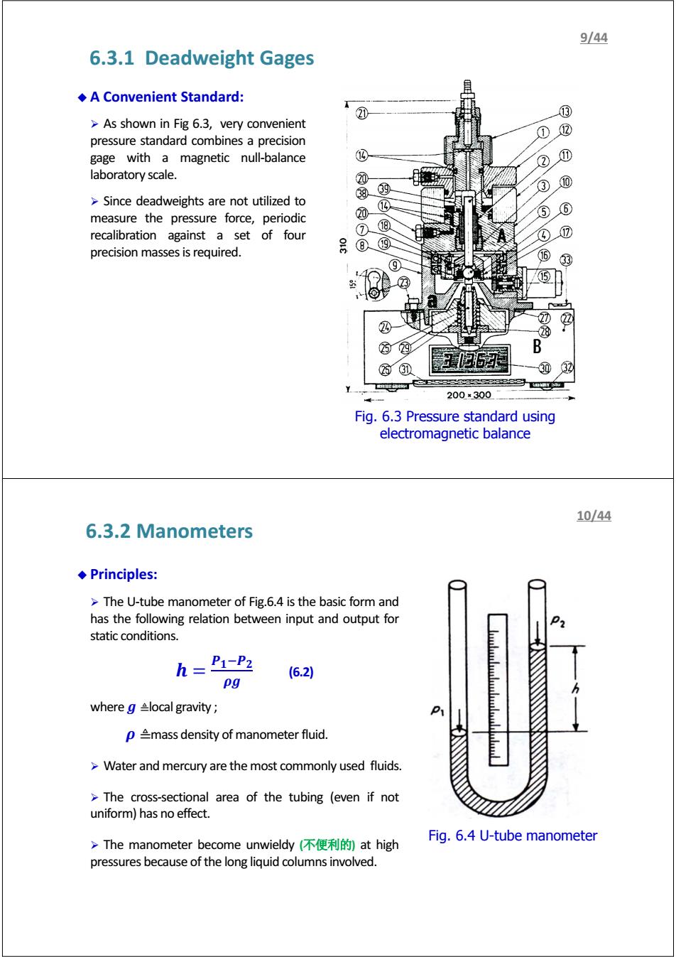
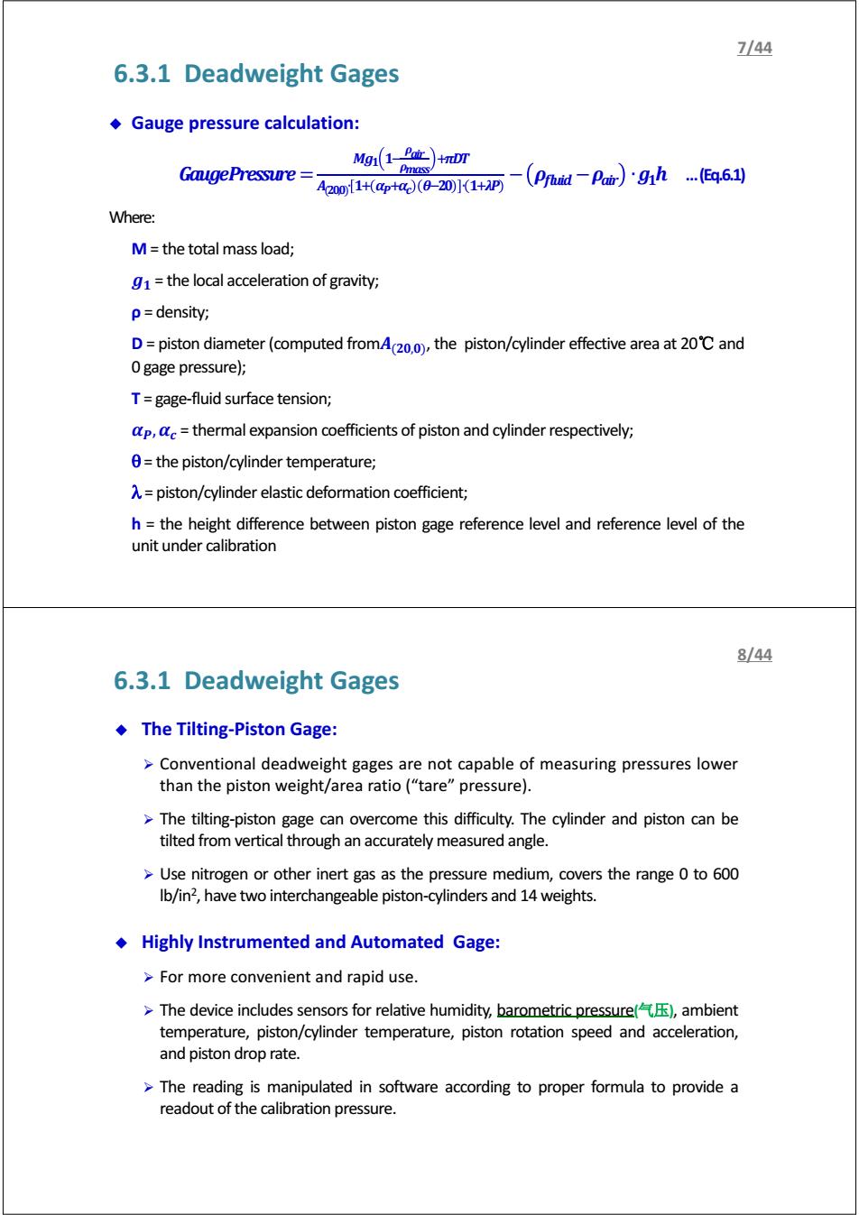
9/44 6.3.1 Deadweight Gages A Convenient Standard: 2① ③ >As shown in Fig 6.3,very convenient ① pressure standard combines a precision gage with a magnetic null-balance ① laboratory scale. 0 ③ ⑩ >Since deadweights are not utilized to ⑩ ⑩ ⑤ 6 measure the pressure force,periodic recalibration against a set of four ⑦@ 号⑧四 ④ precision masses is required. 16 ⑨ 33 15 2 2 B 西① 3四32 Y 200×300 Fig.6.3 Pressure standard using electromagnetic balance 10/44 6.3.2 Manometers ◆Principles: >The U-tube manometer of Fig.6.4 is the basic form and has the following relation between input and output for static conditions. h=P1-P2 (6.2) pg where g local gravity p mass density of manometer fluid. >Water and mercury are the most commonly used fluids. The cross-sectional area of the tubing (even if not uniform)has no effect. Fig.6.4 U-tube manometer >The manometer become unwieldy(不便利的at high pressures because of the long liquid columns involved
6.3.1 Deadweight Gages A Convenient Standard: ¾ As shown in Fig 6.3, very convenient pressure standard combines a precision gage with a magnetic null-balance laboratory scale. ¾ Since deadweights are not utilized to measure the pressure force, periodic recalibration against a set of four precision masses is required. Fig. 6.3 Pressure standard using electromagnetic balance 9/44 6.3.2 Manometers Principles: ¾ The U-tube manometer of Fig.6.4 is the basic form and has the following relation between input and output for static conditions. ࡼିࡼ ൌ ࢎ ࢍ࣋ (6.2) where ࢍ≜ local gravity ; ࣋≜ mass density of manometer fluid. ¾ Water and mercury are the most commonly used fluids. ¾ The cross-sectional area of the tubing (even if not uniform) has no effect. ¾ The manometer become unwieldy (不便利的) at high pressures because of the long liquid columns involved. Fig. 6.4 U-tube manometer 10/44